 |
This task shows you how to save
in IGES format the data contained in a CATPart, CATProduct or a
CATShape document. However, if you
re-import an IGES file made from a CATShape, you will create a CATPart.
|
 |
- IGES 5.3 (year 2000-compliant) is the standard supported.
- Only ASCII 1-byte characters are supported.
The table entitled What about the Elements You
Export ? provides information on the entities you can export. |
|
You can find further information in the Advanced Tasks:
and in the Customizing
3D
IGES Settings chapter.
Statistics about each export operation can be found in the
report file created. |
 |
-
Open the CATPart or CATProduct document to be saved in
IGES format.
-
Select the File > Save As... command.
The Save As dialog box is displayed.
-
Specify the name of the document in the File name:
field.
-
Set the .igs extension in the Save as type
field.
-
Click the Save button to confirm the operation.
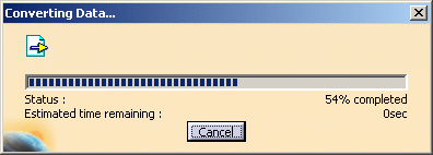
| A progress bar is displayed. |
 |
| You can use the Cancel button to interrupt the transfer at any
time. |
|
 |
- In V5, documents can be exported to files with the extension
"igs".
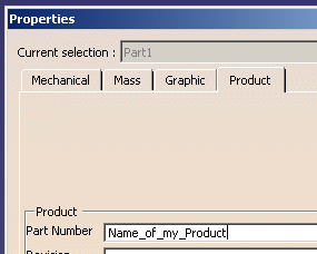
- The part number of the CATProduct is exported as the
Product identification for Receiver.
- The name of the
author and of the organization can be exported to the Global Section
of the IGES file.
- Layer None is translated into layer 10000
in the IGES file.
|
|
Several 3D IGES export options can be customized:
|
|
 |


|
- If the representation mode is "Surface",
the topology of solids and shells is lost during the export.
As a consequence, you have a group of surfaces called an Geometrical set.
If you make an Import with Join, you can get a Close Body.
- You can choose the
export unit.
- Alternative representations that can be selected using Manage
Representations are not taken into
account during STEP exports. The main representation is always exported.
|
| |
- The name of the elements to export must be in ASCII format.
- Overridden faces colors are
supported.
- You export the final construction object, i.e. the whole specification
tree and its history up to the feature at
the bottom of the specification tree and not the current feature: for
example, you wish to export
the specification tree up to Pocket.1 only.
In this case, although Pocket.1 is the current feature, you will
export all elements of
the specification tree including Copy of Pad.1. |
 |
If you want to limit your export to Pocket.1, you have to make
sure that it is the feature at the
bottom of the specification tree, like this: |
 |
|
| |
V5 Element |
IGES Element |
 |
| |
 |
null |
0 |
 |
| |
circle |
circular arc |
100 |
However, in B-Spline mode (see
options), all planes and surfaces are exported to rational B-Spline
surfaces (128) and all curves, circles and lines are exported to B-Spline
curves (126) |
| |
curve, line, circle |
composite curve |
102 |
 |
| |
curve |
conic arc - ellipse |
104 form 1 |
However, in B-Spline mode (see
options), all planes and surfaces are exported to rational B-Spline
surfaces (128) and all curves, circles and lines are exported to B-Spline
curves (126) |
| |
point, curve |
copious data |
106 form 2 |
 |
| |
plane |
unbounded plane |
108 form 0 |
Construction unbounded planes (supporting faces) are
exported as type 108, forme 0.
Independant unbounded planes are not exported.However, in B-Spline mode
(see
options), planes and surfaces are exported to rational B-Spline surfaces
(128) and all curves, circles and lines are exported to B-Spline curves
(126) |
| |
line |
line |
110 form 0 |
| |
Semi-bounded lines |
line |
110 form 1 |
|
| |
Unbounded lines |
line |
110 form 2 |
|
| |
point |
point |
116 |
A point belonging to a sketch is exported only if the sketch
contains only points. |
| |
surface |
ruled surface |
118 |
However, in B-Spline mode (see
options), all planes and surfaces are exported to rational B-Spline
surfaces (128) and all curves, circles and lines are exported to B-Spline
curves (126) |
| |
surface |
surface of revolution |
120 |
| |
surface |
tabulated cylinder |
122 |
| |
matrix |
transformation matrix |
124 |
| |
curve |
rational B-spline curve |
126 |
 |
| |
surface |
rational B-spline surface |
128 |
 |
| |
surface boundary |
curve on parametric surface |
142 |
In standard export mode:
If the surface support is of B-Spline type and C2 continuous, both
representation of boundaries are defined (2D parametric and 3D model
space). Otherwise, only the 3D representation is defined.
In B-Spline mode all surfaces are exported as B-Spline surfaces (with 2D
and 3D boundary representations). Those boundaries are ordered and oriented. |
| |
surface |
trimmed (parametric) surface |
144 |
 |
| |
Solid |
Manifold Solid B-Rep Object Entity |
186 form 0 |
To export those entities, the
Representation mode: Solid - Shell option must be active.
It requires IGES 5.3 or higher. All those new IGES entities have not
been "tested" (IGES Norm 5.3) and the IGES/PDES Organization recommends that
special consideration be given when implementing certain untested entities.
Therefore if you do not know whether the receiver system will recognize
those entities, we recommend that you do not use this option.
For Loops, only the 3D Representation is exported |
| |
Plane Surface (support of Face) |
Plane Surface Entity |
190 form 0 |
| |
Solid (Closed) Shell |
Closed Shell Entity |
514 form 1 |
| |
Independent Shell |
Open Shell Entity |
514, Form 2 |
| |
Face in a Shell |
Face Entity |
510 form 1 |
| |
Face Loop |
Loop Entity |
508 form 1 |
| |
List of Loop Edges |
Edge Entity |
504 form 1 |
| |
List of Start/End Loop Edges Vertices |
Vertex Entity |
502 form 1 |
| |
Long names (more than 8 characters) |
Name Property Entity |
406 form 15 |
|
| |
Color |
color definition |
314 |
 |


![]()

