|
How to Create a Topology
|
 |
This task shows you how to generate the model topology if it
is not contained in the CATPart corresponding to
the original IGES file you have imported.
You have seen how to recover a
maximum of the face geometry and individual
topology, when it failed during
the import of either IGES.
This scenario will show you how to create solids from IGES faces and also
how to join the surfaces of an IGES
model into a Part.
It also shows you how to improve the quality of the geometry of the solid
obtained thanks to the Healing operation
in Generative Shape Design. I
Therefore, this methodology allows you to improve IGES data
interoperability and productivity (use of features).
|
 |
It can also be applied to a STEP file, when the failure of the topology
transfer occurs (in rare cases) and
to improve geometry quality. |
|
Previously, you had 2 scenarios about the repairs of KO faces:
|
|
Now, with the following steps you will learn how to close the topology:
|
|
|
|
Create a topology
|
 |
-
Open the file
01_FaceKOrepaired.CATPart.
-
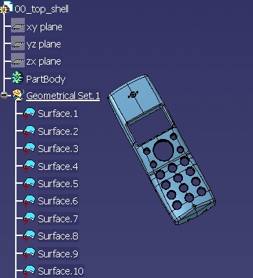
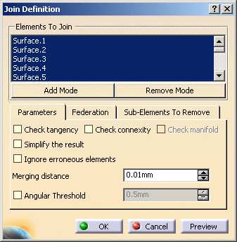
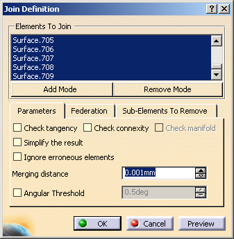
Select all surfaces of GeometricalSet.1 in order to apply
the Join operation upon all these elements.
The Join operation allows to repair geometry whereas
topological healing allows to close topology.
It is better to select the surfaces in the tree
(select Surface.1, then select the last surface holding the Shift key)
to have them ordered by their numbers in the Join Definition dialog
box. |
 |
-
Keep merging distance = 0.001mm and
deactivate the connexity Check option.
The problem is not yet to check whether the surface is closed or even
connex.
This will be analyzed in the following step.
-
Click Preview.
An error message is displayed, saying that some surfaces cannot be
integrated to the join.
 |
| The solution is to withdraw these surfaces. |
-
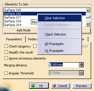
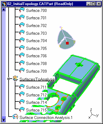
The rejected surfaces are automatically selected in the
list, in the Join Definition dialog
box and you can use the Remove Mode button.
-
Click Apply.
-
Click OK. The resulting join surface includes all surfaces
of GeometricalSet.1 except
those that have been rejected.
-
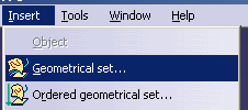
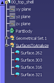
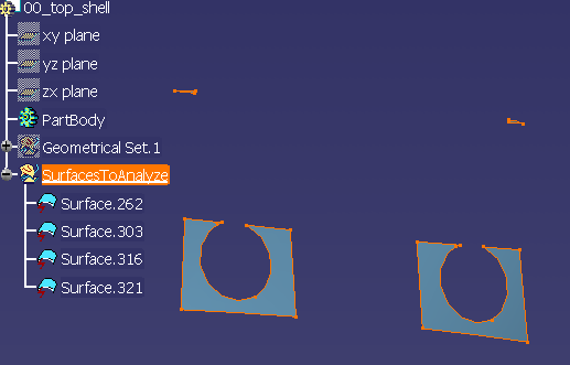
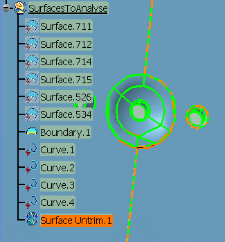
Insert a new Geometrical set and name it SurfacesToAnalyze
(for example).
-
Move the rejected surfaces to the new Geometrical set. For
this, right click them in the
No Show space and
select the Change Geometrical set... contextual command.
-
Hide GeometricalSet.1 and display the other geometrical
set SurfacesToAnalyze.
-
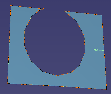
Check the rejected surfaces. Usually rejected surfaces
have a very sharp corner, for instance,
a vertex where edges arrive tangent to each other.
-
Reframe on the first surface to recreate (Surface.321 for
instance):
-
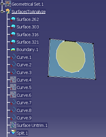
Create its complete boundary by selecting the Boundary
icon  in the Operations toolbar. in the Operations toolbar.
-
Disassemble the boundary in order to be able to see the
curves by using the Disassemble
icon  in the Join-Healing toolbar.
As a result, details about the curves contained in Surface.321 in the Join-Healing toolbar.
As a result, details about the curves contained in Surface.321
are displayed in the Specification tree.
-
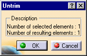
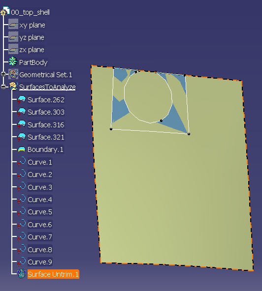
Untrim the surface to process (Surface.321) by clicking on
this icon  Click OK when this
message appears : Click OK when this
message appears :
 |
| A new element is displayed : SurfaceUntrim.1 |
 |
-
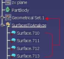
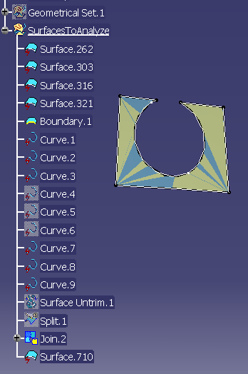
Recreate the face by Split between Surface.710 and
Curve.1, Curve.2 and Curve.9.
-
Join Curve 4, 5, 6 into Join.2
-
Split the surface (in datum mode) with:
- Element to cut: Split.1.
- Cutting element: Join 2.
|
 |
Repeat the same operations with the other rejected surfaces. You
may also recreate only two of them
and use asymmetry for the other two. |
-
Double click Join.1 (in GeometricalSet.1) to edit it and
select the four corrected faces to add them
to the list (Add Mode):
-
Click OK.
| All the surfaces are now inserted into the join: the topology
is complete. You can now delete SurfacesToAnalyze. |
|
|
|
|
Analyze the topology
|
 |
-
Open the file
02_InitialTopology.CATPart.
-
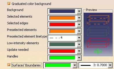
Activate the Surface boundary display option: select the
Tools > Options... command,
click General > Display in the list of objects to the left of
the Options dialog box. Select the Visualization tab.
|
|
|
|
|
 |
The Analysis is based on the free sides of the surface. Free
sides may indicate:
- gaps between elements
- missing elements (not converted or not available in original IGES
file)
- overlaps (duplicated elements)
- invalid elements (with unexpected shapes)
|
| |
-
Double click the join surface Join.1 in the
GeometricalSet.1 to change its merging distance parameter.
Set it to 0.01mm (maximum possible value).
|
 |
Increasing the merging distance will reduce the number of free sides due
to gaps.
It is a way to highlight the most important holes. |
| |
-
Click Preview, then OK.
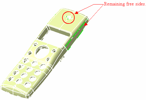
Few free sides remain: three on the top surface and two on the
sides (symmetric to each other).
Now you have to find the type of free side (gap, missing element,
overlap, invalid shape). |
 |
-
Reframe on the side surface surrounded by a free side.
-
Display the No Show space to see the original surfaces.
-
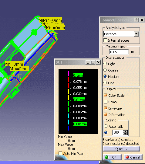
Use the Connect Checker
 in the Analysis toolbar to measure
the distance between in the Analysis toolbar to measure
the distance between
the surface (Surface.707) and its neighbors. The maximum distance is 0. It
means that the free side is not due to gap.
-
Select the surface and send it to the visible space. Check
it you see a hole instead.
There is no hole, it means that this surface was duplicated. You have to
delete one of the surfaces.
-
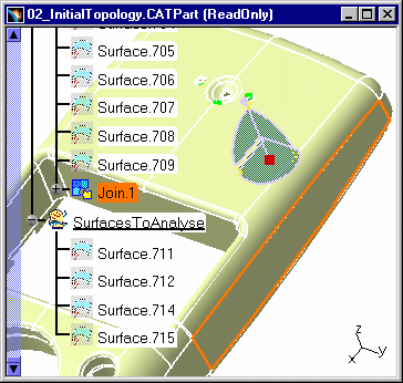
Remove the surface 707 from Join.1, then delete it.
-
Repeat these steps with surface 706.
-
Reframe on the area shown below and display the No Show
space to see the original surfaces
(Surface.526, Surface.534).
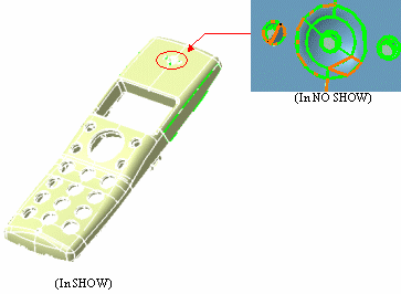 |
They are obviously incorrect, their shapes look strange. The
shaded display is typical of a problem in
the definition of the boundaries (missing boundary curves, wrong
order). |
-
Remove them from Join.1 into SurfacesToAnalyze.
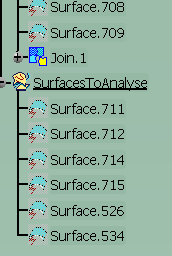
Then for each of the three faces to rebuild,
-
Create the full boundary of the surface.
-
Disassemble the boundary.
-
Untrim the surface.
-
Check the boundary curves and create the missing ones
-
Recreate the correct surfaces by Split (in datum mode).
-
Add the recreated surfaces to Join.1.
The surface has now no visible free side, but there might be
very small holes impossible to detect visually. |
| |
| |
| |
| |
 |
To make sure that the surface is closed: Select Join.1 and
click the Boundary icon.
If the selected surface is closed, you get an explicit message.

It means that the surface is closed within 0.1mm. |
 |
You may now try to reduce the merging distance to find the minimum value
that gives a closed surface.
Change the merging distance to 0.01mm and check for free sides: The
surface is closed within 0.01mm.
Check with 0.005mm: The surface has visible free sides.
Check with 0.008mm: The surface is closed within 0.008mm.
This distance is a good evaluation of the model accuracy. |
|
|
|
Healing
|
 |
-
You may open the file
03_ClosedTopology.CATPart.
At that stage, you may decide that the evaluated accuracy is good enough
but you may also create a solid
and use the Healing to reduce the gaps between surfaces by actually
modifying (deforming) the surfaces.
-
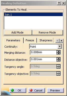
Select the Healing icon
 . .
-
Select Join.1.
-
Give the value of the tolerance found in the previous step
(Merging distance is 0.008mm in this case).
-
Click OK.The surface is now both topologically and geometrically closed.
|
|
|
|
Create a solid
|
 |
-
You may open the file
04_HealedTopology.CATPart.
-
Start a Part Design workbench.
-
Select the Close Surface icon
 in the Surface-Based Features
toolbar. in the Surface-Based Features
toolbar.
-
Select Join.1 or Healing.1. The following message confirms
the operation:
-
Click OK.
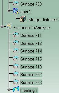 |
| The solid is created and ready for use. The process is now
completed. |
|
|
 |
