- General IGES options:
- Import IGES options:
- Export IGES options:
General
Show/NoShow Completion Dialog Box

By default, the Show Completion Dialog Box option
is not selected.
Select this option to display the completion dialog box at
the end of the transfer.

Import
Import mode
![]()
When the Generate one CATPart option is selected, the IGES file is translated into one CATPart.
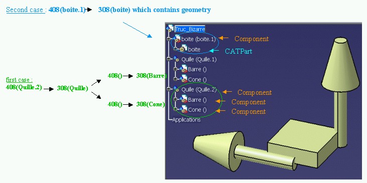
For large files containing a large number of 308/408 IGES entities, you can select the option Map the 308/408 IGES entities onto a Product Structure:
- if the IGES file contains 308/408 entities, a root CATProduct is created in V5,
- the 408 entities will be translated into CATParts or components under
the root CATProduct as follows:
- If the 408 entity references an intermediate 308 entity (i.e. one that contains 408 entities), a new component is created. It will contain components for each 408 of the 308 (see first case below).
- If the 408 entity references a leaf 308 entity (i.e. one that does not contain any 408 entity), a CATPart will be created. It will contain the geometry contained in this 308 (see second case below).

Join
![]()
-
Select the option Join surfaces of the model if you want to join the surfaces of your IGES model into a shell.
If this option is active, the software will try to knit the surfaces from an importable file into a shell, even if the file contains Groups (402).
- If you select the join option, while importing IGES files to V5, make sure that model is constituted of one part.
- The Join operation may fail in specific topological configurations.
- This option does not apply to Manifold Solid Brep (IGES type 186): the faces are always imported into a join.
- The previous option Join surfaces of each group is replaced by the Map the 308/408 IGES entities onto a Product Structure above. This option enables you to create several CATParts from one IGES file.
- When the Map the 308/408 IGES entities onto a Product Structure option is active, the option Join surface of the model is selectable but has no effect.
Continuity Optimization of Curves and Surfaces

V5 requires its geometry to be C2-continuous. When non
C2-continuous geometry must be imported from a IGES file, this geometry
(curves, surfaces) is broken down into a set of contiguous geometries, each
of them being C2-continuous. This is what happens when the No Optimization
option is chosen.
However, this can produce an increase of the size of the resulting data,
because more curves/surfaces are created. In order to limit this drawback,
two other modes are optionally offered.
In those modes, the IGES interface tries to limit the splitting of curves
and surfaces by modifying their shape slightly, so that they become
C2-continuous while remaining very close to their original shape.
In order to guarantee that the deformation is not excessive,
a maximum deviation (tolerance) parameter is used. When in Automatic
Optimization mode, the value read from the IGES file is corrected so
that it remains lower than the default tolerance. This guarantees an optimization that
remains compatible with the precision for the data that was set by the
emitting system.
Last, if this strategy is not enough, you can choose the Advanced
Optimization mode, in which an arbitrary deviation value can be entered.
By default, the Automatic Optimization is proposed:
- No approximation , thus this option does not create a significant deformation and keeps the internal BSpline structure (equations and knots).
- A continuity optimization is performed within the default value for deformation tolerance on:
- BSpline surfaces,
- all types of curves with the exception of canonical curves (3D and P-curves when available),
- The parameters box cannot be activated
This option soften the effect C2 cutting of faces and boundaries (which is mandatory in V5) without any significant geometric deformation
If you select No optimization:
- No optimization is performed on BSplines (neither curves nor surfaces).
- Elements are cut at discontinuity points to suit the modeler (exact mathematic continuity). This may result in a dramatic number of faces and boundary curves, data of poor quality and poor performances in further use in V5.
If you select Advanced Optimization:
- No approximation. The internal BSpline structure (equations and knots) is kept,
- A continuity optimization is performed on:
- BSpline surfaces,
- all types of curves (3D and P-curves when available),
- but the deformation tolerance is set by the user (see Parameters).
With this option, you can enter a larger tolerance value which may enhance the optimization impact (resulting in less C2 cutting on faces.
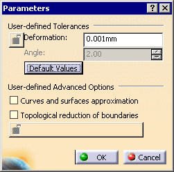
Click Parameters to access advanced optimization options and tolerances.
The dialog box looks like this if you have selected Standard Scale:

User-defined Tolerances
Note that the tolerance is shared by the optimization
process (in all cases), the Curves and surfaces approximation and the
Topological reduction of boundaries if you have selected those check boxes.
For example, you have a deformation tolerance of 0.001mm and
you have selected Curves and surfaces approximation.
The tolerance for the optimization will be 50%, i.e. 0.0005mm and that of
the Curves and surfaces approximation will also be 50%.
Thus, the number of cuts of the faces will vary according to
the value entered, and according to the number of check boxes selected.
-
Angle: angle (in degree) below which contiguous elements can be merged. Ranges between 0 and 10 degrees.
-
Click Default Values to revert to the default values.
The parameters values apply to all current options
User-defined Advanced Options
By default, these options are not selected.
-
Curves and Surfaces Approximation alone:
- BSpline surfaces and curves continuity is optimized,
- In addition, Bspline curves and surfaces approximation is performed,
- It is possible to enter a user value for Deformation,
- This option may change the internal structure of BSplines (equations and knots),
- This option usually results in a significant decrease in the number of faces cuttings.
-
Topological Reduction of Boundaries alone:
- BSpline surfaces and curves continuity is optimized,
- In addition, topological reduction is applied to boundaries,
- The Angle value is used to select contiguous curves that can be merged into a smooth one (tangency criteria),
- It is possible to edit the values for Deformation and Angle,
- This combination of options usually results in a significant decrease in the number of boundary curves (especially on poor quality input data).
- Curves and Surfaces Approximation and Topological Reduction of Boundaries together:
- BSpline surfaces and curves continuity is optimized
- In addition, BSpline curves and surfaces approximation is performed and topological reduction is applied to boundaries
- It is possible to enter user values for Deformation Tolerance and tangency Angle.
- This combination of options allows the utmost optimization of curves and surfaces, while keeping geometric deformation under control. It results in reducing the number of faces and boundaries and ensures better performance in downstream use of the data.
You can find useful information in the report file. Please see the Report file section in the IGES Import chapter in this User's Guide.
Detection of Invalidity in Input Geometry
The dialog box looks like this for the Standard Scale:

You can choose to import IGES files with or without
detecting discrepancies in geometry, by selecting the corresponding option.
Detection enables you to enter the Tolerance
value above which a geometry is considered as invalid:
- size of a hole in an open boundary,
- distance between the boundary loop and the surface.
The default Tolerance value is 3 mm for the
Standard Scale
For more information, please see the IGES Best Practices
chapter in this User's Guide.
Representation for Boundaries of Faces
![]()
There are two type of IGES faces: types 144 and 143. The boundaries of those faces (respectively type 142 and 141) have two representations:
- 2D (parametric)
- 3D (spatial).
For each boundary, the IGES file contains a parameter defining the preferred representation:
- 3D,
- 2D,
- none,
- equal preference.
In the three last cases, V5 tries to import the 2D representation of the boundary. In case of failure, the 3D representation is imported.
By default, the Keep File Preference option is active:
- if the preference is set, the import will respect it.
- if no preference is set, the 2D representation is preferred.
If you do not wish to use the 2D representation (i.e. override the preference set in the IGES file), select the Force 3D representation option. Only the 3D representation will be imported.
Import Groups
![]()
Imports IGES groups (Entity Type 402, Forms 1-7-14-15: Associativity
Instance) as Selection Sets.
You can de-select this option for a faster import. Note that Selection
Sets will not be created.
Export
Save only shown entities
![]()
- When selected, the Save only shown entities option allows you to save only the Part's entities which are in the Show mode.
Curve and surface type
![]()
- The default Standard option and the BSpline
option allow you to select which curve and surface types you want to be
generated.
If you leave the default Standard option selected the curve and surface types created in the Part are kept as is.
If you select the BSpline option all curves and surfaces are converted into B-splines.
Representation mode
![]()
- If you select the default option Surface, solid
decomposition will be identical in both the original model and the
resulting file.
Only the surfacic decomposition of the original model is stored. - Wireframe should be used if you want 3D visualization of
solid edges to be identical in both the original model and the resulting
file.
Only the wireframe decomposition of the original model is stored.
This may be useful in cases where curves are the only form of input accepted.
- Solid-Shell lets you save Solids, Shells and Faces as IGES New Entities as follows:
| V5 | IGES | |
| Solid | Manifold Solid B-Rep Object Entity (Type 186, Form 0) | |
| Solid (Closed) Shell | Closed Shell Entity (Type 514, Form 1) | |
| Independent Shell | Open Shell Entity (Type 514, Form 2) | |
| Face in a Shell | Face Entity (Type 510, Form 1) | |
| Face Loop | Loop Entity (Type 508, Form 1) | |
| List of Loop Edges | Edge Entity (type 504, Form 1) | |
| List of Start/End Loop Edges Vertices | Vertex Entity (Type 502, Form 1) | |
| Plane Surface (support of Face) | Plane Surface Entity (Type 190, Form 0) |
- For Loops, only the 3D Representation is exported
- All those new IGES entities have not been "tested" (IGES Norm 5.3) and the IGES/PDES Organization recommends that special consideration be given when implementing certain untested entities. Therefore if you do not know whether the receiver system will recognize those entities, we recommend that you do not use this option.
- The representation mode Solid-Shell requires IGES version 5.3 or higher.
Author's Name and Organization
![]()
Enter here your name and the name of your organization.
This information will be transferred to the Global
Section of the IGES file at export.
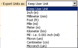
Export Units as
Let's you define the unit to be used for export. This unit can be
different from the V5 file.
The default option is Keep User Unit, the IGES file unit will
be :
- the unit defined in Tools > Options > General > Parameters and Measure / Units tab, if the IGES Norm recognizes it,

- the Millimeter (mm) otherwise.
