Once imported, the data can be handled just as if it were created as a CATPart. Sometimes, some entities are degenerated during the transfer and it is characterized by a loss of geometry. In this case, the missing geometry must be re-created.
In this tutorial you are going to learn how to:
Open the IGES file
-
Open the IGES file FaceKO.IGS into your desktop.
-
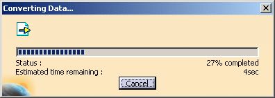
When you open this document, the conversion of the IGES file is progressive and you can visualize the process through this panel:
-
Eventually, once the transfer is completed (see Show/NoShow Completion Dialog Box for more details), a message similar to this one appears:

-
Click OK to continue.
-
All the faces reported as KO are put in the geometrical set GeometryFailure.
For each face KO, you will find a FaceKO.xx geometrical set under GeometryFailure. This geometrical set contains the geometric elements of the face. By default it is sent to the NoShow. 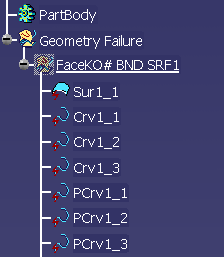
Repair KO faces
-
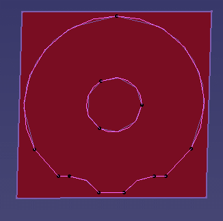
Recall FaceKO#BND_SRF1 from the NoShow and expand it if necessary. It contains the support surface and boundary curves corresponding to the face.
The reason of the failure is that the inner boundary is described before the outer boundary, in contradiction with the IGES standard.
-
In Generative Shape Design (for example), select the Join icon
 .
. -
Select the curves of the outer boundary:
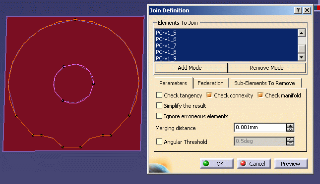
Click OK. A Join.1 is created under FaceKO.1. -
Repeat this step with the curves of the inner boundary:
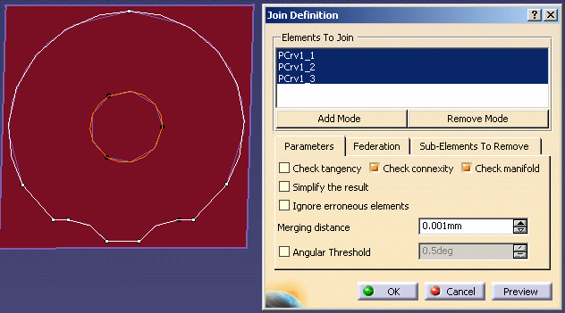
A Join.2 is created under FaceKO.1. -
Select the Split icon
 .
. -
Select the surface and Join.1
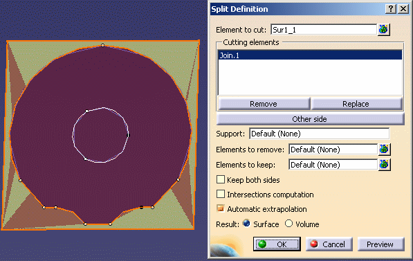
-
Push the Other side button to keep the inside of the surface.
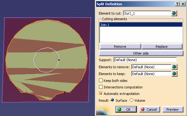
-
Click OK. The surface is split by the outer boundary. Split.1 is created under FaceKO.1.
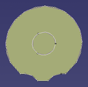
-
Repeat this step with Join.2 and Split.1
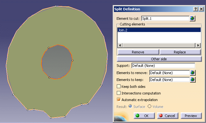
Split.2 is created, corresponding to the repaired face. 

-
If necessary, you can move the result surface Split.2 to another geometrical set: Right click the result surface and select Split.2 object > Change geometrical set... to move the resulting surface to another geometrical set.
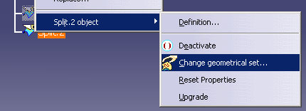
The following dialog box opens. Choose the destination geometrical set: 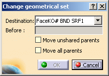
-
Delete the FaceKO#BND_SRF1 geometrical set. All these elements are however present within the No Show space.
Another possible cause of failure:
The splitting operation has kept the wrong side of the boundary.
-
Recreate the correct face by Fill
 (in datum mode).
As a result, a Surface.xx is created.
You may also extract the surface boundary and untrim the surface to use Split.
- please refer to the next chapter entitled IGES: Best Practices - How to create a topology
- or use the application Healing Assistant for more complex cases.
![]()