 |
This task explains how to create an offset
surface, based on an existing surface. |
 |
Open the
FreeStyle_Part_39.CATPart document. |
 |
-
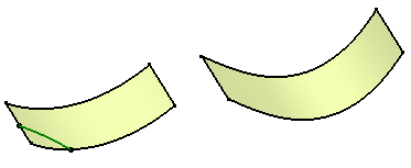
Select a surface, or a set of surfaces.
|
| |
|
|
-
Click the Offset icon
 . .
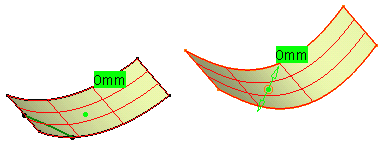
The offset surface is automatically visualized as a meshed surface.
|
| |
|
| |
-
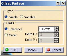
Choose the options you wish from the Offset Surface
dialog box:
|
| |
|
|
-
the offset
type: a simple offset creates a surface which points
are all at the same distance from the initial surface,
whereas a variable offset lets you set the offset distance
at each corner point of the surface.
-
the limits,
that is constraints to be taken into account when computing the offset
surface. You can specify whether it should comply with a given
tolerance,
or it should have a maximum order in U and V. The resulting
surface will lie within these constraints.
-
Display,
that is the elements to be displayed on the geometry.
|
 |
When you click the More... button:
the type of information to be displayed on the offset surface before it
actually is created. This information is useful to let you fine-tune the
offset specifications. |
| |

|
| |
- Offset values: the distance between any point of the
initial surface and the resulting surface.
- Normals: identifying the direction of the initial
surface. Click on the arrow to invert the offset.
- Order: the order value in U and V
- Tolerance: the exact tolerance deviation
- Corners: displays or hides the manipulators at the four
corner points (only in Simple mode) to make Snap on
Geometry possible. When you are in Variable mode, the
Corners option is checked: if you pull the central
manipulator, all manipulators are temporarily linked to each other,
basically they have the same behavior as regular control points.
|
|
-
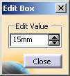
By default the Edit dialog box is displayed. If not,
right-click the offset value box on the surface to display it, and enter
the offset value.
|
| |
|
|
-
Click Close to validate the offset value.
You can also move the pointer over one of the corner points, and
directly pull on the displayed manipulators.
The offset value is dynamically modified.
|
|
-
Click OK in the Offset Surface
dialog box to create the offset surface.
|
| |
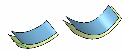
|
|
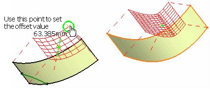
You can also select a
point either in the 3D or in the specification tree to impose the offset
value.
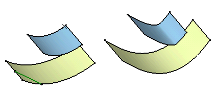
The value will be set as well as the distance corresponding to the normal
projection of the input point onto the surfaces. |
|
|
| |
|
 |
If no projection is possible, no selection is
possible and a message error is issued. |
|
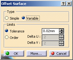
You can also create variable offset: |
| |
|
| |
-
Click Variable in the Offset Surface dialog
box.
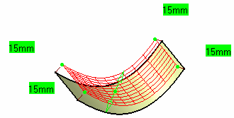
-
You can modify the delta in order.
This means that the maximum order number of the offset surface will not
exceed the initial surface order number plus the indicated value. Offset
values are displayed at each corner of the surface.
-
Move the pointer over a corner point and drag it in the
desired direction to dynamically modify the value.
|
| |
|
| |
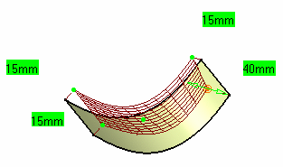
-
Right-click another offset value and using the Edit
dialog box, change this value.
Here we modified two values from 15 to 40.
|
| |
|
| |
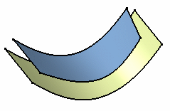
-
Click OK in the Offset Surface dialog box.
The offset surface is created.
|
| |
|
 |
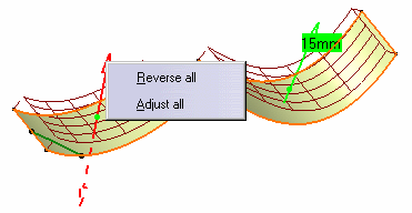
- The same method applies when offsetting a set of surfaces. As all
surfaces may not present the same orientation,
check the Normals option from the Offset Surface dialog box
and right-click arrows: a contextual menu displays on each arrow and
enables you to Reverse or Adjust all.
|
|
|
|
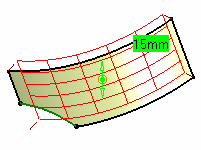
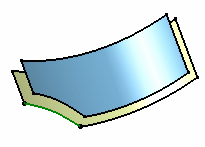
- If the offset is performed on a surface relimited using the break
command, the result is a relimited surface,
even though the pre-visualization presents the initial (not relimited
surface):
|
|
 |
|
|
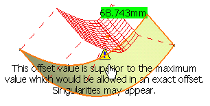
- If the offset value is superior to the maximum value, an error
message is issued. Nevertheless, you can create the offset.
|
| |
|
 |
Multi-selection of surfaces is available. |
 |
Capabilities are available from:
|
|

|
![]()

