This task shows you how to create internal load sensors in a:
Sensors are already available to measure solution output
values (displacement, stress).
The aim of internal load sensor is to provide the resultant of the internal forces and
moments applied on specified nodes of an element selection.
The load resultant is based on free body loads (forces and moments). The computed loads are used to remove the applied loads from the resultants if you specify it.

Only available with the ELFINI Structural Analysis (EST) product.
Internal load sensors are only available in a static case and a multi loads static case.
Open the sample62.CATAnalysis document from the samples directory.
-
Compute the first static solution. To do this:
- Select Static Case Solution.1 in the specification tree.
- Click Compute
 and click OK.
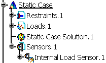
Static Case
![]()
-
Right-click the Sensors.1 set in the specification tree and select Create Resultant Sensor > Internal Load Sensor
 .
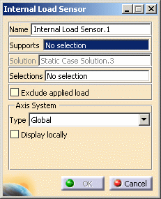
.The Internal Load Sensor dialog box appears.
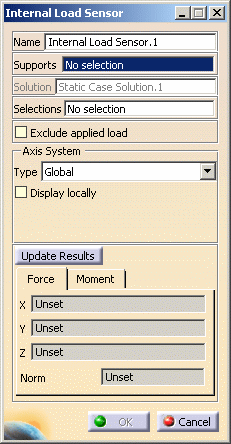
- Name: lets you modify the name of sensor you create.
- Supports: lets you select the nodes on
which the sum for the resultant is to be performed.
The support cannot be empty, it must contain at least one node to
get a resultant.
Non homogeneous multi selection is available.
The support can be a:- Geometry (point, edge, face)
- Mechanical feature (part body, joint, ...)
- Group (geometrical, spatial, by proximity, by boundary).
- Solution: gives you information about the name of solution set in which you are creating the sensor.
- Selections: lets you select the
elements that
constitute the free body.
Non-homogeneous multi selection is available.
You can select:- Geometry (edge, face)
- Mechanical feature (part body, joint, ...)
- Group (geometrical, spatial, by proximity, by boundary).
This selection is not mandatory. If you do not select anything, then the whole geometry constitutes the free body and is taken into account: in this case the whole body is considered to constitute the free body.
- Exclude applied loads: lets you
exclude the applied loads
from the resultant loads.
Applied loads are the loads applied to the nodes constituting the free body.
Resultant loads are computed using the internal load sensor. - Axis System: lets you choose the type
of axis in which the internal load sensor will be computed.
To know more about the axis system, refer to Axis System Type. - Update Results: lets you launch the
computation of the internal load sensor.
If the solution is not up-to-date, this button first launches the solution computation and then the sensor computation. - Force: lets you view the force output characteristics (the X, Y, Z components and the norm).
- Moment: lets you view the moment output characteristics (the X, Y, Z components and the norm).
-
Select the desired Supports.
In this particular case, select Box Group.2 in the specification tree.
-
Select the desired Selections.
In this particular case, select Box Group.1 in the specification tree.
-
Select the desired Axis System.
In this particular case, select Global.
-
Click Update Results.
The output parameters are displayed in the Force and Moment tabs.
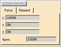
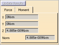
The Internal Load Sensor.1 sensor appears in the specification tree.
Note that the internal load sensor is already updated.
-
Click OK.
-
You can update a sensor (you just have created or modified) or you can update all the sensors belonging to a sensor set.
-
You can display the value of knowledge parameters in the specification tree.
For more details, refer to Displaying Values of Sensors. -
You can also generate a report once the sensor set is updated.
Multi Loads Static Case
![]()
-
Set the third Static Case as the current one.
To do this, refer to Changing a Current Analysis Case.
-
Compute the third static solution. To do this:
- Select Static Solution.3 in the specification tree.
- Click Compute
and click OK.
-
Right-click the Sensors.3 set in the specification tree and select Create Resultant Sensor > Internal Load Sensor
.The Internal Load Sensor dialog box appears.
- Name: lets you modify the name of sensor you create.
- Supports: lets you select the nodes on
which the sum for the resultant is to be performed.
The support cannot be empty, it must contain at least one node to
get a resultant.
Non homogeneous multi selection is available.
The support can be a:- Geometry (point, edge, face)
- Mechanical feature (part body, joint, ...)
- Group (geometrical, spatial, by proximity, by boundary).
- Solution: gives you information about the name of solution set in which you are creating the sensor.
- Selections: lets you select the
elements that
constitute the free body.
Non homogeneous multi selection is available.
The support can be a:- Geometry (edge, face)
- Mechanical feature (part body, joint, ...)
- Group (geometrical, spatial, by proximity, by boundary).
This selection is not mandatory. If you do not select anything, then the whole geometry constitutes the free body and is taken into account: in this case the whole body is considered to constitute the free body.
- Exclude applied loads: lets you exclude the loads applied to the nodes constituting the free body from the resultant loads computed using this sensor.
- Axis System: lets you choose the type
of axis in which the internal load sensor will be computed.
To know more about the axis system, refer to Axis System Type.
-
Select the desired Supports.
In this particular case, select Box Group.2 in the specification tree.
-
Select the desired Selections.
In this particular case, select Box Group.1 in the specification tree.
-
Select the desired Axis System.
In this particular case, select Global.
-
Click OK.
The Internal Load Sensor.1 sensor appears in the specification tree.
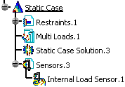
Note that the internal load sensor is not updated.
To see the values of the internal load sensor, you have to generate a report.
To do this: -
Update the Sensors.3 set.
-
Right-click Sensors.3 and select Report.
To know more about the Report contextual menu, refer to Generating Reports.
An html report is displayed. This file contains the value of the internal load sensor you created.
You can update a sensor (you just have created or modified) or you can update all the sensors belonging to a sensor set.
![]()