This task shows you how to select a:
The list of the available axis system types depends on the functionality.
Axis systems are used in the definition of loads, restraints, connection properties (for example: force, advanced restraint, stiffness). The components of this force, advanced restraint or stiffness will be interpreted as relative to the specified coordinate system.
Left-handed axis systems are not supported.
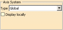
Global Axis System
|
|
The Display locally check box is not always
available. |
If you select the Global axis system, the components will be interpreted as relative to the fixed global rectangular coordinate system.
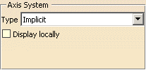
Implicit Axis System
|
|
The Display locally check box is not always
available. |
If you select the Implicit Axis system, the components will be interpreted as relative to a local coordinate system computed on the selected support.
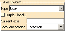
User-defined Axis System
|
|
The Display locally check box is not always
available. |
- Current axis: lets you select the axis system you choose
as reference axis system.
This axis must be created in the Part document. - Local orientation:
lets you choose between three local coordinate systems (Cartesian, Cylindrical, Spherical)
in which the components are interpreted as relative.
- Cartesian:
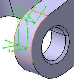
Axis is built locally at any point P of the support as shown below: 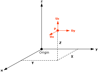
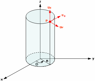
- Cylindrical:
Axis is built locally at any point P of the support as shown below: 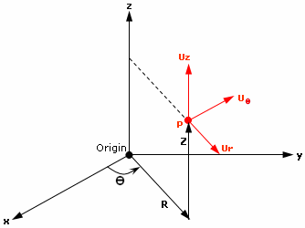
Uz is collinear to z, where z represents the revolution axis of a cylinder.
Ur and UΘ are respectively the radial and tangential components in the plane which is perpendicular to the z axis.
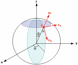
- Spherical:
Axis is built locally at any point P of the support as shown below: 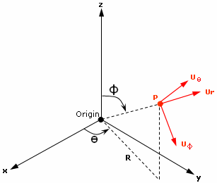
The origin of the local axis system is at the node of interest (P). So for each node of the support, a local axis is built.
Ur, UΘ and UΦ are respectively the radial, circumferential and meridionial components.
- Cartesian:
Display Locally
This option lets you display the selected axis system locally on the geometry.
|
|
The Display locally check box is not always
available. For example:
|
![]()