This task shows you how to transfer image content (coordinates, values, axis system if needed) into a .txt, .xls or .3dxml file. This can be performed in the case of hybrid or non-hybrid models.
Only available with the ELFINI Structural Analysis (EST) product.
- This contextual menu is valid only for images with the
following positions:
- Node
- Element
- Center of element
- Node of element.
- The exported data (for example, the number of the nodes)
depends on:
- The advanced parameters selected in the Image Edition dialog box
- The selection of elements that you choose to visualize on a generated image
- Whether you selected or not the On boundary
option in the Color Map Editor dialog box.
To know more about the color palette, refer to Editing the Color Palette.
Open the sample35.CATAnalysis document from the samples directory.
- Compute the solution.
- Generate several images.
In this particular example, click Deformation ,
then click Displacement
 and
finally click Von Mises Stress
 .
.
Export Data in .txt or .xls File
-
Right-click Translational displacement vector.1 in the specification tree and select Export Data
 .
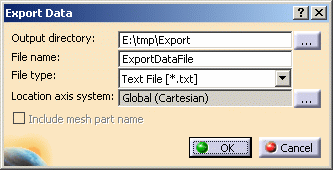
.The Export Data dialog box appears.

- Output directory: lets you select the directory in which the data will be exported using the Choose Directory dialog box.
- File name: lets you choose the desired file name.
- File type: lets you choose the
type of the file in which the data will be exported. This file type can be either
.txt, .xls or .3dxml.

- Text File [*.txt]: lets you export
image data in a .txt file.
Not available for the Mesh and Deformed Mesh images. - 3D XML File [*.3dxml]: lets
you export image data in a .3dxml file.
In this particular example, the .3dxml format is not available.
For more details, refer to Export Data in .3dxml File. - Microsoft Excel Worksheet [*.xls] (not
available on Unix):
lets you export image data in a .xls file.
Not available for the Mesh and Deformed Mesh images.
- Text File [*.txt]: lets you export
image data in a .txt file.
- Include mesh part name: lets you
indicate the name of the mesh part in the export file.
Moreover, if you work in the analysis assembly context, you will also export the name of the product instance.
To know more about this option, refer to Exporting Mesh Part Name and Product Instance Name.
This option is available only with images generated at element position.
In this particular example, this option is not available because the displacement image is generated at node position.
-
Select the desired Output directory.
-
Modify the file name if needed.
-
In the File type list, select Text File [*.txt].
-
Click OK.
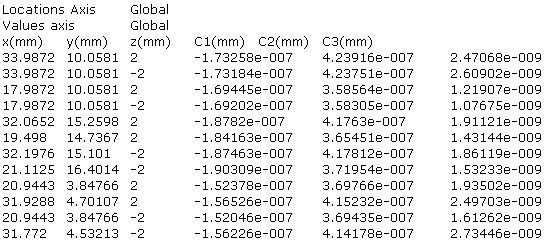
You can find below an extract of the exported data file :

-
Double-click the Translational displacement vector.1 image to edit it.
The Image Edition dialog box appears.
To know more about this dialog box, refer to Image Edition. -
Change the image parameters.
In this particular example:
-
Click More>>.
-
Click ... to change the Axis system.
-
Select Spherical in the Coordinate system list.
-
Click OK in the Image Axis System dialog box.
-
Select C1 in the Component list.
-
Click OK.
-
-
Generate an other export data file on the edited image.
You can find below an extract of the exported data file:

Note that information regarding the axis system has changed and the coordinates have been added. Moreover, only the values of the C1 component have been exported in the file.
Export Data in .3dxml File
3D XML is an XML-based format lets you share 3D data. Post-processing images can be exported in a 3DXML format.
You can export images in a 3DXML format and at the same time, you can export its associated color palette and a legend.
To know more about the .3dxml format, refer to 3D XML Format in the Infrastructure User's Guide.
-
The .3dxml format is not available for Symbol and Text visualization modes.
-
Texture on 1D elements is not saved in the .3dxml format.
-
To save lines in the 3dxml format:
-
Select Tools > Options... in the menu bar.
-
Select the Infrastructure > Product Structure category.
-
Select the Save lineic elements in cgr check box in the Cgr Management tab.
-
-
To save textures in the 3dxml format:
-
Select Tools > Options... in the menu bar.
-
Select the General > Compatibility category.
-
Select Exact or Compressed tessellation in the 3D XML tab.
-
-
Right-click Von Mises Stress (nodal values).1 in the specification tree and select Export Data
 .
.The Export Data dialog box appears.
To know more, refer to the description of the dialog box. -
Select the desired Output directory.
-
Modify the name if needed.
-
In the File type list, select 3D XML File [*.3dxml].
-
Click OK.
Three files are automatically generated in the directory you specified:
- A .3dxml file that contains the 3D representation.
- A .bmp file that contains the color palette.
No color palette is displayed for Mesh and Deformed Mesh images, so in the case of these two images, no .bmp file is generated. - A .txt file that contains the legend with detailed information about the exported image.
You can now use these generated files as desired.
For example, you can insert the .3dxml and .bmp files in a Word document.
Export Axis System Definition
The values of the axis system are exported.
The exported values depend on the axis system selected in the Image Edition dialog box.
-
Global axis system:
-
Cartesian:

-
Cylindrical:

The three first Values axis are the origin coordinates, the next three values are the X-axis coordinates and the last three values are the Y-axis coordinates.
The exported values will be interpreted as cylindrical coordinates in this global axis system. -
Spherical:

The three first Values axis are the origin coordinates, the next three values are the X-axis coordinates and the last three values are the Y-axis coordinates.
The exported values will be interpreted as spherical coordinates in this global axis system.
-
-
User axis system:

The three first Values axis are the origin coordinates, the next three values are the X-axis coordinates and the last three values are the Y-axis coordinates.
Moreover the exported file indicates whether the coordinate system is:
- Cartesian
- Cylindrical
- Spherical
-
Manual axis system:

The three first Values axis are the origin coordinates, the next three values are the X-axis coordinates and the last three values are the Y-axis coordinates.
Moreover the exported file indicates whether the coordinate system is:
- Cartesian
- Cylindrical
- Spherical
-
Local axis system (for example, an export data on Stress principal tensor (symbol) image)

where:
- (ux, uy, uz) are the coordinates of the X-direction of the local axis for the point (x, y, z).
- (vx, vy, vz) are the coordinates of the Y-direction of the local axis for the point (x, y, z).
The Z-direction is given by the cross product of X and Y.
Export Mesh Part Name and Product Instance Name
The Include mesh part name lets you export the
name of the mesh part in the export file.
Moreover, if you work in the analysis assembly context, you will also
export the name of the product instance.
This option is available only with images generated at element position.
Single Analysis
-
Click Principal Stress
 in the Image toolbar.
 -
Double-click this image to edit it.
In this particular example:
-
Click More>>.
-
Select Center of element in the Position list.
-
Select C11 in the Component list.
-
Click OK.
-
-
Right-click the edited image and select Export Data.
-
Select the Include mesh part name check box.
-
Click OK.
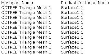
The export data file contains the name of the mesh part.
You can find below an extract of the export data file:

Analysis Assembly
- Open the sample14.CATAnalysis document from the samples directory.
- Compute the static solution.
-
Click Principal Stress
 in the Image toolbar.
 -
Double-click this image to edit it.
In this particular example:
-
Click More>>.
-
Select Center of element in the Position list.
-
Select C11 in the Component list.
-
Click OK.
-
-
Right-click the edited image and select Export Data.
-
Select the Include mesh part name check box.
-
Click OK.
The export data file contains both the name of the mesh part and the name of the product instance.
You can find below an extract of the export data file:

![]()