Offset functionality:
- Allows to add an offset to a selected set of shapes (surfaces or
volumes), this provides a security margin around these shapes
- Enables to define the orientation in which the offset is applied. This orientation can be changed manually or automatically to correct the possible lack of uniformity between the orientation vectors of the different surfaces.For more detailed information, refer to More About Offset along Normal Vectors.
You can manage automatically your Offset result as alternate shape of the initial component. In this case, the offset result will be automatically reinserted and will replace the initial component (provided the Activate check box is selected, it is by default)
Note: If your are not working in alternate shape mode, it is strongly recommended to use the Reference Product option to avoid positioning problems when reinserting products. Please read About Reference Product
-
Click the Offset icon
 in the DMU Optimizer toolbar.
The Offset dialog box is displayed. -
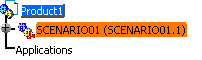
Select the solid or surface you want to work on (i.e. SCENARIO0. model) either in the specification tree or in the geometry area.

The result can be surface or a solid. The type of the offset result will be the same. -
Enter the Offset value, 2mm for instance.
Note: you can define an offset along fixed vectors, please refer to the
Generating Offset Along Fixed Vectors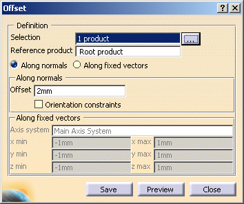
-
Click the More button:
The Input Products dialog box is displayed
The listed selection corresponds to the those products you selected before you launched a calculation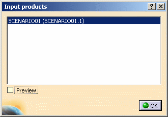
You can select the Preview check box to see a preview of you product selection -
Click Preview to generate the offset representation.
The Preview window is displayed: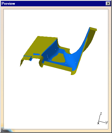
-
Zoom to visualize better the offset result.
If you are not satisfied with the result (because of gaps between surface patches or bad offset orientation)
You may use the Orientation constraints optionOrientation Constraints
- The Orientation constraints option is disabled by default. (The default normal vectors are used)
- Using this functionality, you can define the orientation of the
offset (on every surface patch).
- If you select the
Orientation constraints check box (without defining
additional vectors): the normal vector orientation is calculated
automatically. The first normal vector found defines the
reference orientation which is propagated to the neighboring
surfaces.
- If the automatic propagation is still incomplete (for example, some surfaces are not correctly connected), you need to define manually normal vectors.
- If you select the
Orientation constraints check box (without defining
additional vectors): the normal vector orientation is calculated
automatically. The first normal vector found defines the
reference orientation which is propagated to the neighboring
surfaces.
-
Select the Orientation constraints check box in the dialog box still displayed:

-
Click Apply.
The Propagation is not complete. The surfaces concerned are highlighted. -
Select the Orientation constraints check box again to define constraints on the initial representation.
-
Define constraint vectors for the corresponding surfaces in the document window:
- Drag the cursor onto the surface.
- When you are satisfied, click the left-hand mouse button.
The constraint vector is created.
At anytime, you can delete a constraint vector, what you need to do is to click on the white square
Note that if you click the arrow, you reverse the constraint vector orientation. -
Click Apply when done. The calculation is based on the orientation of the constraint vectors.
This time, the result is correct (there is no longer highlighted surfaces):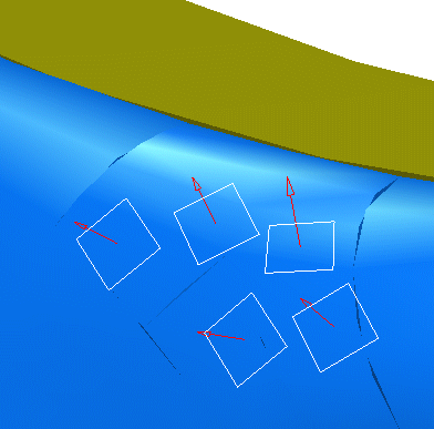
-
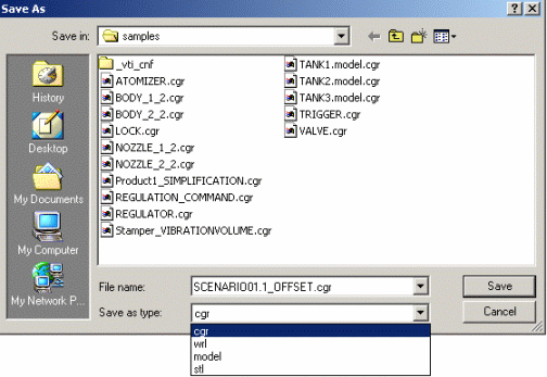
Click OK.
The Save As dialog box is displayed: -
Enter a meaningful name and save in .cgr format.
-
Click Save
Alternate Shape:
(Optional)
You can manage automatically your Offset result as alternate shape of the
initial component.
For this:
- Select Tools->Options from the menu bar.
The Options dialog box is displayed - Expand the Digital Mockup category from the upper-left tree.
- Select DMU Optimizer item to display the corresponding tab.
The Alternate Shapes Management is available - Select the Offset check box: the offset is automatically
treated as an alternate shape

The Offset result will be added to the initial component as a new representation (it will replace the original component). For more details, please refer to Customizing DMU Optimizer Settings and Managing as an Alternate Shape.
![]()