Offset functionality:
- Allows to add an offset to a selected set of shapes (surfaces or
volumes), this provides a security margin around these shapes.
- Enables to define the vectors along which the offset is applied. These vectors are defined either from the product main axis system or from any axis system in a .CATPart document (Part Design workbench, Axis System command).
You can manage automatically your offset result as alternate shape of the initial component. In this case, the offset result will be automatically reinserted and will replace the initial component (provided the Activate check box is selected, it is by default)
Note: If your are not working in alternate shape mode, it is strongly recommended to use the Reference Product option to avoid positioning problems when reinserting products. Read About Reference Product
-
Click the Offset icon
 in the DMU Optimizer toolbar.
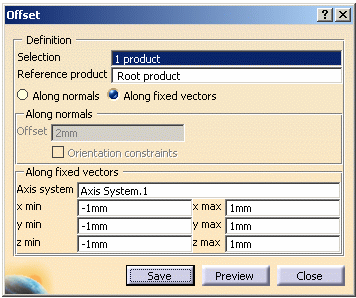
The Offset dialog box is displayed. -
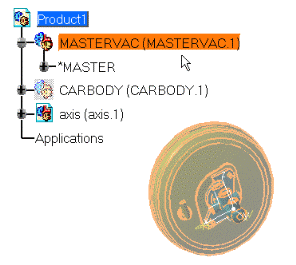
Select the solid or surface you want to work on (i.e. MASTERVAC (MASTERVAC.1) in the specification tree or in the geometry area.
-
Select the Along fixed vectors check box. The along fixed vectors frame is no longer grayed out.

Note: Refer to Generating an Offset along Normal vectors for the Along normals mode -
If necessary, click in the Axis system area and select the axis system which defines the offset directions (the default axis system is the product main axis system)
- i.e. select Axis System.1 either in the geometry area or in the specification tree.
-
Enter the required offset values in the x, y and z fields:
- x min: -20mm
- x max: 20mm
- y min: 0mm
- y max: 0mm
- z min: 0mm
- z max: 0mm
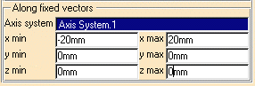
For more detailed information refer to Fixed vectors in More about Offset. -
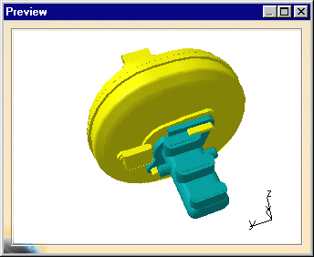
Click Preview to generate the offset representation.
The Preview window is displayed: -
Zoom to visualize better the offset result.
-
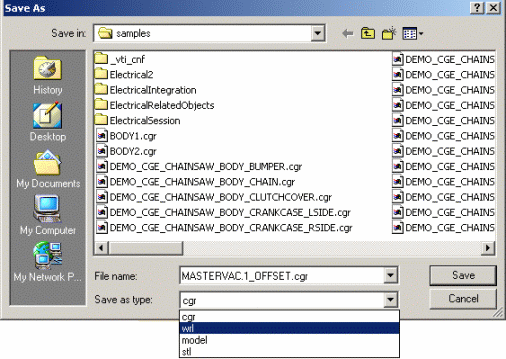
Click Save to save the result.
The Save As dialog box is displayed: -
Enter a meaningful name and save in the desired format (.cgr, .vrml or.CATIA model)
For more detailed information, please read About saving operations -
In our example, save your result MASTERVAC.1_OFFSET in cgr format.
-
Click Close to exit the offset command
Alternate Shape:
(Optional)
You can manage automatically your Offset result as alternate shape of the
initial component.
For this:
- Select Tools->Options from the menu bar. The Options dialog box is displayed
- Expand the Digital Mockup category from the upper-left tree.
- Select DMU Optimizer item to display the corresponding tab.The Alternate Shapes Management is available
- Select the Offset check box: the offset is automatically
activated as an alternate shape

The Offset result will be added to the initial component as a new
representation
For more details, please refer to Customizing DMU Optimizer Settings and
Managing as an Alternate Shape.
![]()