- How is the Offset Representation Calculated?
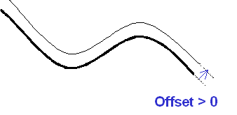
- Case 1: offset value > 0
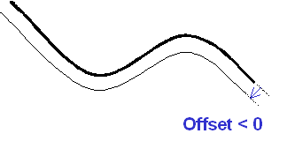
- Case 2: offset value < 0
- Orientation Constraints Option Impact
- Orientation Constraints Check box Cleared
- Orientation Constraints Check box Selected
- Orientation Constraints Option Selected and Two Orientation Constraint Vectors Defined
- Unresolved Cases
How is the Offset Representation Calculated?
The offset representation is obtained by:
- Adding an offset to a selected set of shapes (surfaces or volumes), this provides a security margin around these shapes
- defining the orientation in which the offset is applied.
or/and if necessary:
- changing this orientation manually or automatically to correct the possible lack of uniformity between the orientation vectors of the different surfaces.
The offset value can take any positive or negative values.
The following example aims at illustrating the impact of the offset value on the final result.
 |
Case 1: offset value > 0

Case 2: offset value < 0
 |
Orientation Constraints Option Impact
Sometimes you will tackle with design inconsistencies. You can check the
orientation constraints and/or define orientation constraint vectors to
force the orientation of the offset.
This procedure can be used when different surface patches are assigned
opposite normal vectors.
The following example aims at illustrating the orientation constraints option.
Orientation Constraints
Check box Cleared
The default normal vectors define the offset orientation.
 |
Result: If the surface patches are not correctly designed, there might be gaps between the different surface patches. In this case, you need to use the orientation constraints option (automatic mode)
NB. You should study the result preview carefully to detect
inconsistencies.
Orientation Constraints Check box
Selected
The first default normal vector defines the offset orientation reference. This orientation is propagated to the neighboring surfaces.
 |
Result: If the surface patches are not correctly connected,
there might still be remaining gaps between surface patches. In this case,
you need to use the orientation constraints option and to define manually
constraint vectors.
NB. The surface patches are not correctly connected are highlighted
in the result preview.
Orientation constraints option
selected and two orientation constraint vectors defined
 |
Result: The surface patches are now correctly connected (there
is no longer highlighted surfaces)
NB. The constraint vectors defined manually appear as red arrows on
the picture.
Unresolved Cases
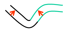
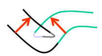
Offset and thickness operations are not boolean, therefore, be careful when you deal with acute angles and high offset values because you might encounter overlapping surfaces. See pictures below:
 |
| Offset value still in a good range |
 |
| The angle is too "sharp" and/ or a too high offset value is set. |