This task illustrates how to make the most of section
viewer capabilities:
Accessing the Section Result Window capabilities
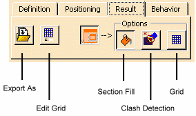
Most of the commands described in this task are to be found in the Result tab of the Sectioning Definition dialog box or in the Section result window contextual menu.
|
|
|
|
Step-by-Step Scenario
![]()
Insert the following cgr files: ATOMIZER.cgr, BODY1.cgr, BODY2.cgr, LOCK.cgr, NOZZLE1.cgr, NOZZLE2.cgr, REGULATION_COMMAND.cgr, REGULATOR.cgr, TRIGGER.cgr and VALVE.cgr.
They are to be found in the online documentation filetree
in the common functionalities sample folder cfysm/samples.
![]()
Before you begin
When dealing with CATProducts containing a large amount of sections, for performance gain purposes, read carefully the Customization recommendations (follow the described procedure).
-
Select Insert > Sectioning from the menu bar, or click Sectioning
 in the DMU Space Analysis toolbar and create the desired
section plane,
slice or
box and corresponding section.
Section Results Window
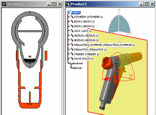
The Section Results window appears alongside the document window (by default, it is automatically open). It displays a front view of the section, and is by default, locked in a 2D view. Points representing the intersection of the section plane with any wire frame elements are also visible in the Section result window.
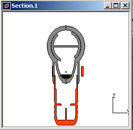 |
When performing multiple sections, you need to
arrange (resizing and positioning) their section result windows
in an appropriate way. From R17 onwards, you can customize the
sectioning result window;
the size and
positioning of the result windows you specify are now kept and thus
persistent.
Customizing the section result window size
Select Tools > Options > Digital Mockup > DMU Sectioning tab.
In the Results window settings category, select the required categories of options and click Ok when satisfied.
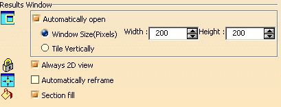 |
|
|
|
Refer to the Customizing section for detailed information. |
 |
|
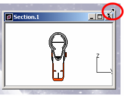 |
Customizing the section result window positioning
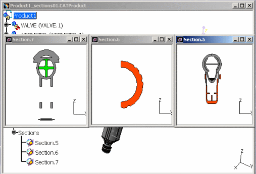 |
Note though that if you select the Tile vertically option in Windows Result area (Tools > Options > Digital Mockup > DMU Sectioning tab) the positioning is forced and automatically defined:
 |
Accessing the section windows
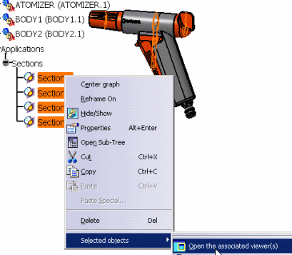 |
About the Section Fill capability
Notice that the section view
is a filled view. This is the default option. The fill capability generates
surfaces for display and measurement purposes (area, center of gravity,
etc.). To obtain a correct filled view, the section plane must completely
envelop the product.
Note: The filled view is not available when the plane sections surfaces.
To obtain an unfilled view, de-activate the Section
Fill
![]() in
the Result tab of the Sectioning Definition dialog box.
in
the Result tab of the Sectioning Definition dialog box.
|
|
|
|
|
|
Orienting the Section
-
Orient the generated section.Flip and Rotate commands are to be found in the contextual menu. Right-click in the Section viewer and:
-
Select Flip Vertical
 or Flip Horizontal
 to flip the section vertically or horizontally 180 degrees.
 -
Select Rotate Right
 or Rotate Left
 to rotate the section right or left 90 degrees.
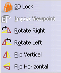

Orienting the section using Flip and Rotate commands is not persistent. If you exit the section viewer, any flip and rotate settings are lost.
-
Working with the 2D Grid
-
Click the Result tab in the Sectioning Definition dialog box, then select Grid
 under Options to display a 2D grid.
  By
default, grid dimensions are those of the generated section. Moving
the section plane re-sizes the grid to results. To size the grid to
the section plane, clear the Automatic grid re-sizing check box in
the DMU Sectioning tab (Tools > Options..., Digital Mockup
> DMU Space Analysis).
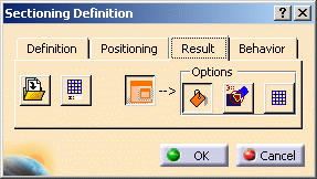
You can edit the grid step, style and mode using the Edit Grid command.

-
Select Edit Grid
 to adjust grid parameters: The Edit Grid dialog box appears:
In the above example, the grid mode is absolute and the style is set to
lines.
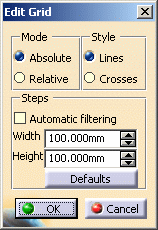
In the absolute mode, grid coordinates are set with respect to the absolute axis system of the document.
The grid step is set to the default value of 100. The arrows let you scroll through a discrete set of logarithmically calculated values. You can also enter a grid step manually.
Units are current units set using Tools > Options (Units tab under General > Parameters and Measure).
-
Scroll through grid width and height and set the grid step to 10 x 10.
-
Click the Relative mode option button: In the relative mode, the center of the grid is placed on the center of section plane.
-
Click the Crosses style.
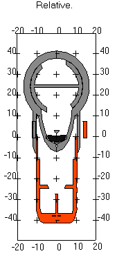
Grid parameters are persistent: any changes to default parameters are kept and applied next time you open the viewer or re-edit the section.
-
Click Automatic filtering check box to adjust the level of detail of grid display when you zoom in and out.
-
Right-click the grid then select Coordinates to display the coordinates at selected intersections of grid lines. The Clean All command removes displayed grid coordinates.
-
Click OK in the Edit Grid dialog box when done.
Working with a 3D View
By default, the Section viewer is locked in a 2D view. De-activating the 2D view lets you:
-
Work in a 3D view and gives you access to 3D viewing tools
-
Set the same viewpoint in the Section viewer as in the document window.
Returning to a 2D view snaps the viewpoint to the nearest orthogonal view defined in the Section viewer.
-
Right-click in the Section viewer and select the 2D Lock command from the contextual menu. The Import Viewpoint command becomes available.
-
Manipulate the section plane.
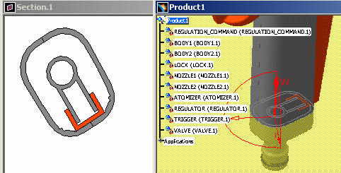
-
Right-click in the Section viewer and select the Import Viewpoint command from the contextual menu. The viewpoint in the Section viewer is set to that of the document window.
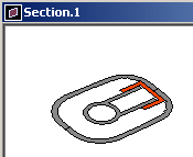
-
Continue manipulating the section plane.

-
Return to a locked 2D view.
The viewpoint in the Section viewer snaps to the nearest orthogonal viewpoint in this viewer and not to the viewpoint defined by the local axis system of the plane in the document window.
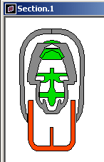
You can also save sectioning results in a variety of different formats using the Export As command in the Result tab of the Sectioning Definition dialog box or the Capture command (Tools > Image > Capture).
-
Click OK in the Sectioning Definition dialog box when done. If you exit the Sectioning command with the Section viewer still active, this window is not closed and filled sections remain visible.
![]()
P2 Functionality -
Detecting Collisions
In DMU-P2, You can detect collisions between 2D sections.
To do so, click Clash
Detection
![]() in the Result tab of the Sectioning Definition dialog box.
in the Result tab of the Sectioning Definition dialog box.
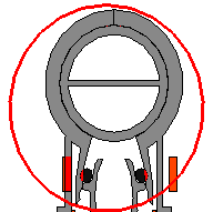
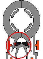
Clashes detected are highlighted in the Section viewer.
|
|
Collision detection is dynamic: move the section plane and watch the Section viewer display being updated.
|
|
Note: Clash detection is not authorized when in the Section Freeze mode.
![]()
