- What Are Bodies Made Of ?
- Specific Mechanisms Locate Features
- Impacts on Existing Capabilities
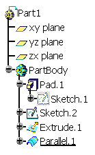
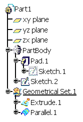
- Sketch Location in the Specification Tree
- Reorder
- Delete
- Surface and Wireframe Geometrical Elements created on the fly
- Surface-based Features
- Visualization
- Creation of features
- Boolean Features
- Power Copies
- Insert Added Volumes
Terminology
A Body created from V5R14 onwards is still referred to as Body. Likewise, when creating a new part, the default body is referred to as Part Body.
Conversely, bodies created using application versions prior to V5R14 are no longer referred to as bodies but as Solid bodies in applications user's guides, not in specification trees.
Graphic Representations
- A Body or PartBody you create in a hybrid design environment is
identified with a green wheel icon in the specification tree:

 .
.
- Solid bodies are identified with gray
icons:


However, from V5R15 onward the green icons identifying existing bodies turn yellow if you change the type of design environment to a non-hybrid design type:
|
|
For further information, refer to Graphic Representations of Bodies and Solid Bodies.
PartBody in a Hybrid Design Environment
Solid body (here PartBody) in a Hybrid Design Environment
What Are Bodies Made Of ?
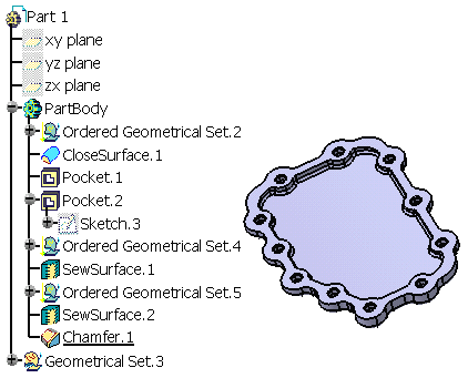
A body has only one solid result. It can contain the following entities:
- All Shape Design features
- Ordered geometrical sets (OGSs): this is possible by using the
Insert > Ordered Geometrical Sets command. For more information,
refer to Inserts Bodies
into Ordered Geometrical Sets.
Creating an OGS within a body is the same as creating an OGS within an OGS. Inserting Part Design Features in OGSs is not allowed. - Sketches
- Boolean Operations
- Solid bodies: you can integrate them into bodies thru Boolean
operations and Copy/Paste mechanisms.
Example of a PartBody
What Bodies Do Not Contain
A body cannot contain the following:
-
Bodies
-
Geometrical Sets
-
Volumes: they cannot be created in a body but they can be created in an ordered geometrical set (OGS) contained in body. To see an example, refer to Inserting Added Volumes.
Specific Mechanisms Locate Features
Up to Version 5 release 14, bodies displayed their contents according to
two major principles: ordering and absorption. Now that they can include
additional feature types, namely surface and wireframe features, both
mechanisms apply to them too. All features in a body are displayed in the
tree so as to show a succession of steps defining the design. In other
words, the order of apparition of features in the specification tree is
consistent with the steps of creation of the design.
Unlike features within a solid body, features in a body can be set as
current: a given step of the design creation is chosen and what is located
after it is not accessible nor visible.
Impacts on Existing Capabilities
Because of new rules to be followed, a certain number of existing capabilities have been upgraded so as to reflect the changes. Here are the new behaviors you now need to be familiar with:
- Sketch Location in the Specification Tree:
up to Part Design Version 5 release 14 the sketches used for creating sketch-based features were located directly below the features in the specification tree. Now, to improve the visibility of your design process this behavior has changed: depending on how sketches are created, sketch entities are displayed or not below the features they support.
For more information, refer to Part Design User's Guide. - Reorder:
After reordering a feature in the specification tree, local objects are defined as follows: the application sets the first feature that is not affected by the reorder operation as the new defined in work object. - Delete:
- In a hybrid design environment, whenever you delete a sketch-based feature, you can choose between deleting the corresponding aggregated sketch or not. In concrete terms, you can activate or deactivate the Delete aggregated elements option.
- Deleting a surface or wireframe element may affect the specifications of a Part Design feature.
- When deleting a Boolean operation, by default all operated bodies (located below the Boolean operation node) are deleted too: just deselect the Delete aggregated elements option if you wish to keep the bodies.
For more information, refer to Part Design User's Guide.
- Surface and Wireframe Geometrical Elements created on the fly
For more information, refer to Part Design User's Guide. - Surface-based Features
For more information, refer to Part Design User's Guide. - Visualization
If you wish to show or hide all the Part Design and Shape Design features belonging to the same body, you need to select the body and then apply the Hide/Show capability. - Creation of features
When creating a new feature in a current body, the geometry that pointed to the feature preceding the new feature is redirected to the new feature you are creating. - Boolean Features:
When performing a Boolean operation, whatever the operation type you perform (Add, Assemble, Intersect etc.), the application displays the specification trees in two different ways. If the sequential construction of the geometry is valid, the Boolean Operation node contains the operating body. Conversely, if you perform a mixed Boolean operation or if there is an interruption of the sequential construction of the geometry, the Boolean Operation node never contains the operating body. - Power Copies
In a hybrid design environment, bodies that underwent Boolean operations are located below the nodes corresponding to these operations. Consequently, they cannot be selected to define a power copy. If, for example, you try to select Body.5 as an input element making up a power copy, a warning message displays warning you that because Body.5 is aggregated into Assemble.3, you cannot select it as an input component.
For more information, refer to Part Design User's Guide.
Insert Added Volumes
The Insert Added Volumes command lets you change from the volume design to solid modeling.