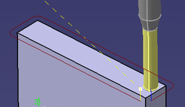
This task shows you how to replay a machining operation.
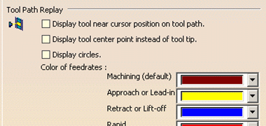
Please note that a number of settings for customizing Tool Path Replay are available in the Tools > Options > Machining > General tab.
The following dialog box appears at the end of the computation. It contains a number of command icons for managing the tool path replay and material removal simulation. The name of the current operation appears in the title bar.
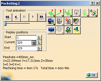
Information that appears in this dialog box includes:
- Current feedrate.
- Current tool tip position (X, Y, Z) and tool axis orientation (I, J,
K).
Note that for turning operations, the IJK components are always set normal to the machining plane.
This IJK vector is not related to the turning tool orientation. - Machining time and total time.
Total time is machining time plus non-machining time (that is, time spent in transition paths and so on). These times are displayed in hh:mm:ss format. Time values are always displayed rounded off to the nearest integer value and with no fractions displayed.
Point to Point
Continuous
Plane by Plane:
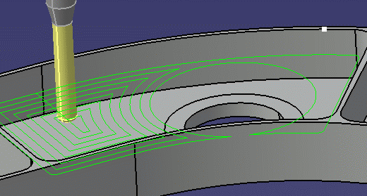
The tool path is displayed by plane. This is suitable for multi-level operations such as Pocketing or Roughing.
Note that consecutive portions of the tool path are displayed at each click on the forward (or backward) control button. All parts of the tool path on the same level may not be displayed together.
Transition paths may be displayed as you click forward (or backward).
Approach and retract paths are displayed in a lower intensity.
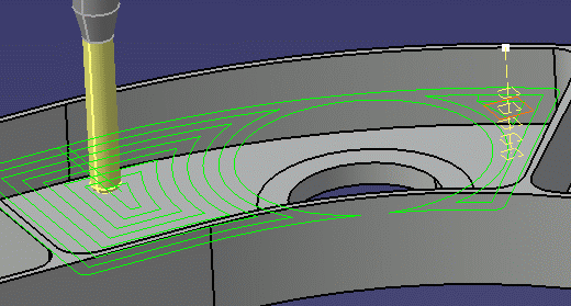
Sectioning:
In this mode the tool path of the operation is sectioned at each level.
The program selects a suitable direction to define the normal to the sectioning planes.
The replay progresses level by level along this normal at each click on the forward (or backward) control button.
All the portions of the tool path are displayed in a given sectioning plane.
This mode is suitable for multi-level operations such as Pocketing or Roughing.
You can choose to display the machined surface with or without the tool axes (see the Tool Visualization modes below).
Feedrate by Feedrate.
Syntax by Syntax:
The replay stops each time a PP instruction is met and the syntax of the instruction is displayed on the trajectory (for example, CYCLE/DRILL,0.000,1.000).
Tool displayed at last position only
Tool axis displayed at each position
Tool displayed at each position
Machined surface is displayed in Sectioning replay mode.
Machined surface and tool axes are displayed in Sectioning replay mode.
Tool path displayed in same color (green by default).
Tool path displayed in different colors for different feedrates. The colors are initialized as follows but they can be customized under the Tools > Options > Machining > General tab.
Yellow: approach or lead-in feedrate
Green: machining feedrate
Blue: retract or lift-off feedrate
Red: Rapid feedrate
Cyan: finishing feedrate
Magenta: plunge feedrate
Cyan: chamfering feedrate
Magenta: air cutting feedrate.
See Using and Customizing Tool Path Colors for more information.
Trajectory of the contact point is displayed
Trajectory of either the tool tip or the tool center point is displayed
Trajectories of the contact point and either the tool tip or the tool center point is displayed
Trajectory of either the contact point or either the tool tip or the tool center point is displayed.
TRACUT instructions are taken into account to display the tool path
TRACUT instructions are not taken into account to display the tool path.
Tool holder is displayed during the replay
Tool holder is hidden during the replay.
This option allows better visibility when checking the tool or tool path with respect to the part. It can be used for default tool assemblies and CATProduct user representations.
or F5 key to position the tool at the operation start point
or F6 key to run the replay backward
or F4 key to request a pause in the replay
or F7 key to run the replay forward
or F8 key to go to the operation end point.
If the F7 or F6 key is kept pressed:
- for point by point, plane by plane, feedrate by feedrate, and syntax by syntax, replay steps are done continuously one after the other
- for continuous replay, the animation speed increases at each refresh.
The input to Start, Current and End positions can be done by either keying in the text boxes in the Replay positions area or selecting from the 3D graphics area. When you click the Start and End position push buttons, the complete tool path is visible temporarily so that desired position can be selected for providing the position input. When Current Position is selected only the tool path between the Start and End positions is shown.
In partial tool path replay, the tool path display is updated according to user input.
In partial/complete replay, the tool display can be updated by using the current position input.
See Partial Tool Path Replay Behavior for more information.
More About Tool Path Replay
Tool Path Replay Considerations
- If the operation has been deactivated by means of the
Deactivate command, it cannot be replayed. If you want to replay the operation, you must reactivate it using theActivate
Similarly, if the manufacturing program has been deactivated, it cannot be replayed. If you want to replay the program, you must reactivate it.
- If a Profile Contouring operation was created with the cutter profile output option, both the cutter profile and tip trajectory will be displayed in the replay.
- If a user-defined tool representation is related to the operation, that tool will be displayed in the replay.
- You can also access the Replay capability directly from the machining operation editor or from the Manufacturing Program dialog box.
- You can select several machining operations in the specification tree in order to simultaneously replay the tool paths associated to these operations.
- When replaying large tool paths, you can control the animation speed
using the Animation speed slider:
- in the first half of the slider, speed goes from one point to 10 points
- in the second half of the slider, speed goes from 10 points to N/10 (where N is the total number of points).
Partial Tool Path Replay Behavior
By default, the partial tool path replay positions are always displayed. Using the input boxes and selection push buttons, you can specify the Start, Current and End positions of the tool path replay.
The Current and End positions displayed are based on the activity
being replayed.
Default values for partial tool path replay positions of any operation are:
- Start position is first point of the tool path
- Current and End positions correspond to the last point on the tool path.
Partial tool path replay can be used for a single machining operation. Replay on Manufacturing Program is also possible and the partial replay positions are for the current operation being replayed. The inputs can be given with respect to the current operation by pausing the replay on Manufacturing Program.
Partial tool path replay is not available for multiple machining operations or auxiliary operations like tool change, transition paths, COPY Operator, machine rotation, and material removal simulation. For any unsupported activity, the replay positions are grayed out.
The information (feed rate, tool path point and tool axis, machining and total time) displayed at the bottom of the tool path replay panel, is consistent with the currently displayed tool path, even if it is partial
Visualization mode and color modes can be specified for partial tool path replay.
Partial tool path replay is not available in Plane by Plane, Feedrate by Feedrate and By Sectioning modes. If you switch to one of these modes, the positions are restored to full tool path and the editor boxes are grayed out. The behavior of these replay modes is then the same as for the complete tool path.
During continuous replay of partial tool path, the Current position spinner box is grayed out and once the replay is completed, the spinner box is updated with the Current position of the tool.
The Start position is always less than the End position. The Current position specified must be between the Start and End positions. The End position cannot be greater than the last tool path position. In case of input position error, the last valid position is retained.
If Start and/or End positions are modified and are both higher/lower than the Current position, the current position is reset to the End position.
All of the replay positions can be re-set to originally displayed values for the current operation by using the contextual menu on the position editor boxes.
Using and Customizing Tool Path Colors
Same Color
When Color mode is set to Same Color ![]() in the Tool Path Replay dialog box, the tool path will be displayed in a
single color. This color is decided by the setting in Color
combo in the Graphic tab of the machining operation's
Properties dialog box.
in the Tool Path Replay dialog box, the tool path will be displayed in a
single color. This color is decided by the setting in Color
combo in the Graphic tab of the machining operation's
Properties dialog box.
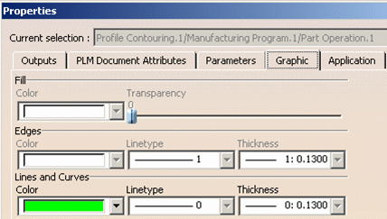
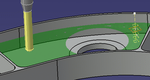
In the example below, the tool path will be displayed in green because green is selected in the Color combo of the Properties dialog box and Color mode is set to Same Color in the Tool Path Replay dialog box. If you want to change the tool path color, you must select the new color in the Properties dialog box.
Different Colors
When Color mode is set to Different Colors ![]() ,
the tool path will be displayed in various colors depending on the
feedrates.
,
the tool path will be displayed in various colors depending on the
feedrates.
These colors are decided by the settings in the Color of feedrates combos in the Tools > Options > Machining > General tab. These settings will override the setting in the machining operation's Properties dialog box.
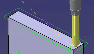
In the example below, the colors for approach, machining, and retract feedrates are set to yellow, burgundy, and blue in the Tools > Options dialog box.
The approach, machining and retract paths will be displayed in these colors because Color mode is set to Different Colors in the Tool Path replay dialog box.
Color of Transitions Paths between Operations
A transition path from operation A to operation B is represented by a dashed line whose color depends on the feedrate. This feedrate is determined as follows:- If a clearance macro is activated operation B, the feedrate of the
clearance path is used for the transition path. For more
information see Start Feedrate option in
Tools > Options.
Note: If Start Feedrate option is not set in Tools > Options and operation B is an axial machining operation, the feedrate is always set to RAPID. - If no clearance macro is activated on operation B, the feedrate
depends on the setting of the
Set Rapid feedrate at start
of operations option in the Generate NC Output dialog box.
- If the option is set, a Rapid feedrate (red) is used for the transition path
- If the option is not set, the first feedrate defined on operation
B is used for the transition path (for example, yellow for approach
or green for machining).
Note: If operation B is an axial machining operation, the feedrate is always set to RAPID.
Color Coding after APT Import
When the tool path replay is done on a machining operation after an APT Import, color feedrate codes are not respected. This is because there is no information about the trajectory type (approach, machining , retract, and so on) in the APT file.
In the case, the trajectory with smallest feedrate value is arbitrarily assigned the machining feedrate color, the trajectory with next higher feedrate value is assigned approach feedrate color, and the trajectory with the next higher feedrate is assigned the retract feedrate color.
Tool Path Computation when Hidden Geometry is Present
Computation depending on the Hide/Show status of selected elements
The following rules summarize the tool path computation behavior depending on the Hide/Show status of selected elements.
- Rule 1: If you select a Body or OpenBody, and use it as Part, Check or Fixture in a machining operation, the tool path will use the Body or OpenBody, regardless of whether it is in Show or Hide status.
- Rule 2: If you select a Body or OpenBody, and use faces (which are sub-elements of this Body or OpenBody) as Part, Check or Fixture in a machining operation, then only the sub-elements which are in Show status will be used during tool path computation. Hidden sub-elements will be ignored in the computation.
- Rule 3: If you select explicitly a set of faces and use them as Part, Check or Fixture in a machining operation, the tool path will use these faces, regardless of whether they are in Show or Hide status.
Influence of selecting 'By boundary of faces' or 'By belt of faces' option
A surface can be selected (both in Hide and Show modes) from the PPR tree using the 'By boundary of faces' option. However, selection from the PPR tree using the 'By belt of faces' option is not possible: selection must be done in the 3D viewer.
The reason for this difference in behavior is described below.
In all cases, the toolpath computation algorithm supports only a contour
of edges.
Then, a contour must be retrieved from the selected faces. This contour
is not created by the same way according to the
'By belt of faces' or 'By boundary of faces' mode.
By boundary of faces:
The edge contour is the external boundary of selected faces.
However, all faces must be topologically connex (they share their adjacent edges). The edges used by the toolpath computation algorithm exist in the design.
By belt of faces:
This situation is more complex because:
- the contour has to be a belt of faces: each face has to be adjacent to only one other face of the belt (except one if the contour is closed).
- the faces have to be ruled only the same axis (tool axis)
- the faces have to be topologically adjacent
- the order of the faces contribute to the stability of the material side in the case where the belt of face is not closed (for Profile Contouring).
The edges used by the toolpath computation algorithm do not exist in the design. To get the contour of edges and the boundary of faces, it is projected onto the bottom plane of the bounding box of the belt, and the wireframe elements (including free vertices) are deleted.
When you select an object in the tree, you don't select the faces but the complete feature whose result can include more than one face. Those faces are not necessary built as a belt of faces. Moreover, the number and position of the faces included in the feature can be modified by the user. In this case, it may not be possible to compute the operation.
Conclusion:
Selection from the PPR tree using the 'By belt of faces' option is not possible. Selection must be done in the 3D viewer.
Material Removal Simulation
![]() You can
use the Photo commands to simulate the material
removed by machining operations in Photo mode (this is a P2
functionality).
You can
use the Photo commands to simulate the material
removed by machining operations in Photo mode (this is a P2
functionality).
![]() You can use
the Video commands to simulate the material
removed by machining operations in Video mode (this is a P2
functionality).
You can use
the Video commands to simulate the material
removed by machining operations in Video mode (this is a P2
functionality).
Machine Accessibility
![]() You can use Check
Reachability to check the accessibility of the part on a machine.
You can use Check
Reachability to check the accessibility of the part on a machine.
Please refer to Accessibility on a Generic
Machine (this is a P2 functionality).
Start Machine Simulation
![]() If the NC Machine Tool Simulation product is installed, you can use
Starts Machine Simulation to
switch to the NC Machine Tool Simulation workbench. Please refer to the
NC Machine Tool Simulation User's Guide for more information.
If the NC Machine Tool Simulation product is installed, you can use
Starts Machine Simulation to
switch to the NC Machine Tool Simulation workbench. Please refer to the
NC Machine Tool Simulation User's Guide for more information.
Note: The Starts Machine Simulation icon is not available if the too path replay is launched during machining operation edition. This is to ensure that simulation is available only if the operation definition is complete.
When the tool path replay is launched directly on a machining operation, then the Starts Machine Simulation icon is available.
![]()