This is done using the Macros tab page
![]() of the machining operation editor. In this example you will
add circular approach, circular retract, and linking macros
to a Profile Contouring operation.
of the machining operation editor. In this example you will
add circular approach, circular retract, and linking macros
to a Profile Contouring operation.
For more general information about macros, see NC Macros.
Predefined Macros
You can use predefined macros. These are made up from one or more paths in a specific order. Just select the desired mode in the Current Macro Toolbox. You can then adjust parameters of the macro (such as path length and feedrate).
User-Built Macros
You can also build your own macros using the Build by user mode.
Depending on the context, you can use the following icons to specify macro paths:
tangent motion
normal motion
axial motion
circular motion
ramping motion

PP word
motion perpendicular to a plane
axial motion to a plane
motion perpendicular to a line
distance along a given direction
tool axis motion
motion to a point.
In addition, the following icons allow you to:
remove all macro paths
remove current macro paths
copy the paths defined on the Approach macro on to the approach paths of other macros or copy the paths defined on the Retract macro on to the retract paths of other macros.
Macro Edition
A sensitive icon representing the elementary paths of the macro will help you to build or edit your macro. The current macro path is colored violet. Right-clicking a macro path gives you access to a contextual menu.
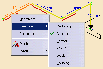
Deactivate: Deactivates the selected macro path.
Activate: Activates a path that was previously deactivated.
Feedrate: Allows you to modify the feedrate type associated to the selected macro path by making a selection in the sub-menu. If local is selected, you can assign a local feedrate value.
Parameter: Gives access to parameters of the selected macro path.
Delete: Deletes the selected macro path.
Insert: Inserts a macro path depending on the type chosen in the sub-menu.
Inherited Macros
If you create a machining operation and there are other operations of the same type in the program, the new operation will inherit the macros used in the most-recently edited operation of the same type. An operation is considered edited when you click OK to quit the operation definition dialog box.
In the Current Macro Toolbox select the Circular horizontal axial mode.
A sensitive icon representing the 3 elementary paths of this macro appears.
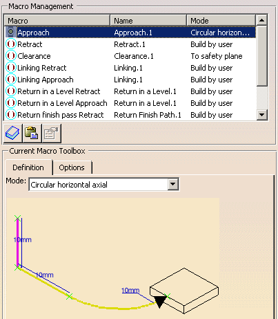
The following dialog box allows you to specify the exact characteristics of the circular path.

Set the values of the circular approach paths so as to have a 10mm vertical path followed by a 15mm radius circular path.
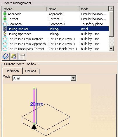
Click Replay to validate the tool path. Make
sure that the Different colors mode is activated
by selecting this icon
![]() in the Tool Path Replay dialog box.
in the Tool Path Replay dialog box.

- Yellow: approach feedrate
- Green: machining feedrate
- Blue: retract feedrate
- Red: Rapid feedrate
- White: user-defined feedrate.
Please note that transition paths are represented by dashed white lines.
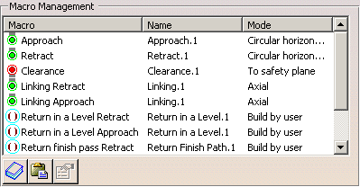
The operation is updated with the specified macros.
PP Words in Macros
You can insert PP words in macros by double-clicking the green X symbols in the sensitive icons.
The PP Words Selection dialog box is displayed. You can enter the syntax in the following ways:
- enter one or more PP word syntaxes directly in the text field
- click
 to access the PP words table that is referenced in the current
part operation. You can then select predefined syntaxes
from this table using the dialog box that appears.
For Pocketing and Profile Contouring operations, you should
select the NC_CUTCOM_ON instruction in the list of available
syntaxes if you want the program to interpret cutter compensation
automatically (that is, by a CUTCOM/LEFT or CUTCOM/RIGHT instruction).
If you choose different syntax in the list, it will be used
as selected.
The methodology for this is described in the section "How to
Generate CUTCOM Syntaxes" in the Prismatic Machining
User's Guide.
Default Linking Macros in Case of Collision
If a user-defined linking macro is not collision free, a default linking macro is applied.
Macro Motion Tangent to Tool Path and Parallel to Tool Axis
When the tangent to the tool path is parallel to the tool axis, the following macro motions are replaced by an axial motion:
- tangent motion
- normal motion
- circular motion
- ramping motion.
 Helix
Approach Macro
For Pocketing, Profile Contouring, Multi-axis Curve Machining
and Multi-Axis Flank Contouring operations, a Helix approach
macro
![]() can be used rather than a Ramping approach macro when a cutter
approaches raw material.
can be used rather than a Ramping approach macro when a cutter
approaches raw material.
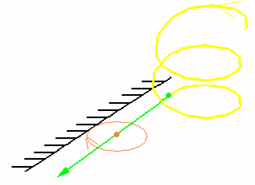
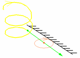
The helix is specified by defining radius, height and angle values.
The figure below illustrates a helix approach macro when
the Direction of cut is Climb and the tool's Way of rotation
is Right:
The figure below illustrates a helix approach macro when
the Direction of cut is Conventional and the tool's Way of rotation
is Right:
![]()