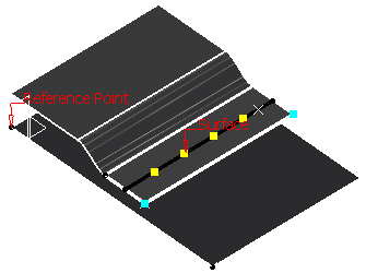
This task shows you how to create a welding spot projection and which one of the connected zones is specified as a projection zone.
- a joint and a joint body are already created: click the desired icon and select the joint body in the selection tree.
- a joint and a joint body are already created: select the joint body in the selection tree and click the desired icon (here is the example used for our scenario).
- no joint body is created. Select the components or the publications, and click the desired icon: a joint and a joint body are created if needed.
Open the Projection1.CATProduct document.
Make sure the SpotProjection Fastener Type is set up in the standard file.
-
Select the joint body in the specification tree.
-
Click BiW Welding SpotProjection
 in the Spot Welding sub-toolbar.
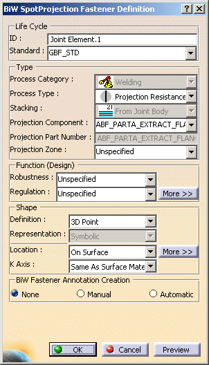
The BiW SpotProjection Fastener Definition dialog box opens. 
-
Specify whether you wish to use the existing standard or not.
If a standard has been imported, a spot projection is created using this standard. If not, you are able to define your own values for each attribute. -
Define the Projection type:
- Projection Component: specifies one of the Joint components
- Projection Part Number
- Projection Zone: specifies one of the Joint Body zones and must belong to the component specified in the Projection Component field.
-
Define the design of the spot projection:
-
Robustness
-
Regulation
-
More>>: allows you to define the Manufacturing parameters.

The shape is necessary a 3D point. -
-
Select the location of the point:
-
On Surface (as in our scenario)
For further information on the location methods, you can click the More>> button. 
-
-
Click OK to create the spot projection.
The spot projection (identified as Joint Element.xxx) is added to the specification tree, under the Joint Body node. 
![]()