This section outlines the technique of creating lighting effects in matrix mode:
If you are not doing lighting calculations, the geometric transformation pipeline is relatively simple. Vertices (vectors) representing positions in 3-D space are transformed into normalized device coordinates (NDCs, that is, 3-D cubes whose x, y, and z coordinates are restricted to lie between -1.0 and 1.0) and then scaled to the physical window (and screen) integer coordinates.
The transformation to NDCs is accomplished by multiplying the input vector by a matrix that represents the combined actions of modeling, viewing, and projection transformations. Each of the individual transformations is represented by a matrix, and these can all be multiplied together to yield one matrix that has the same effect as the sequential application of all the individual matrices. (See "Working with Coordinate Systems"for more information.)
For lighting calculations, the transformation is done in two steps because the calculations require vectors transformed by the modeling and viewing matrices but not yet projected. The mmode subroutine is required to put the system into the two-step mode when lighting is turned on.
In the one-step mode, all transformations are kept on one transformation stack, and all transformation subroutines operate on that stack. In the two-step mode, modeling/viewing transformations are kept separate from the projection transformations. The modeling/viewing transformations are kept on a stack; the projection matrix is kept separately and is not on a stack.
There are three matrix modes: MSINGLE, MVIEWING, and MPROJECTION. The default is MSINGLE, the one-step mode. The system can be placed in the one-step mode by calling
mmode(MSINGLE);
although, by default, it is already in that mode. To use lighting the system MUST be placed in the MVIEWING mode. This is done by making the call
mmode(MVIEWING);
After this call, all matrix subroutines operate on the matrix stack. The getmatrix subroutine returns the top matrix on the modeling/viewing stack; the loadmatrix, multmatrix, rotate, translate, scale, lookat, and polarview all operate on the top matrix of the stack. Note, however, that the perspective projection subroutines (perspective, window, ortho2, or ortho) are an exception: they do not operate on the modeling/viewing stack, but rather affect the projection matrix directly.
If the application needs to define a customized perspective transformation (one that is not covered by perspective, window, ortho, or ortho2) while lighting is turned on, the application should go into MPROJECTION mode by calling
mmode(MPROJECTION);
In this mode all the matrix subroutines operate on the projection matrix. The getmatrix subroutine returns the current projection matrix. The loadmatrix, multmatrix, rot, rotate, translate, scale, lookat, and polarview all operate directly on the projection matrix, as well as the usual projection subroutines (perspective, window, ortho2, and ortho). On the other hand, the pushmatrix and popmatrix calls make no sense in this mode because the stack is not directly accessible. Furthermore, no drawing should be done while in MPROJECTION mode; the system is not configured for drawing when it is in this mode. When you are finished defining the projection matrix, you should go back directly to MVIEWING mode. Please heed the following note of caution:
Attention: Entering or leaving MSINGLE mode scrambles the contents of the matrix stack and leaves the current projection matrix undefined.
When you write a GL program, you must always remember to initialize the transformations. By default, they are NOT pre-initialized by the system. In the one-step mode (MSINGLE mode), a call to loadmatrix or to one of the four projection subroutines (perspective, window, ortho2, or ortho) is sufficient. In the two-step mode, both the projection and the modeling/viewing matrices must be initialized. Again, calls to the projection subroutines are sufficient to initialize the projection matrix; the modeling/viewing matrix can be initialized by a call to the loadmatrix subroutine while in MVIEWING mode.
Normally, you load the identity matrix (a 4x4 matrix with ones running along the diagonal, the other entries zero), although any matrix may be loaded. The initialization is required because most of the matrix subroutines (multmatrix, rot, rotate, translate, scale, lookat, and polarview ) multiply into the current matrix, and if that matrix does not exist, the multiplication cannot take place. Remember, if you intend to use lighting, you must leave MSINGLE mode before performing the initialization.
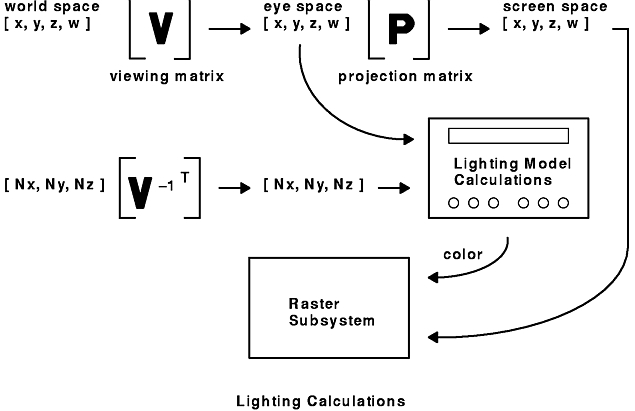
Like vertices, normal vectors associated with the vertices must also be transformed. However, normals are transformed according to different mathematical rules than vertices. For lighting calculations, the normal vectors are multiplied by the inverse transpose of the 3X3 upper left submatrix of the modeling/viewing transformation.
As you operate on the modeling/viewing stack, its inverse transpose is automatically kept up to date.
The getmmode subroutine returns the current matrix mode. The values returned can be compared to the values of MSINGLE, MPROJECTION, and MVIEWING to determine the current mode. Mode identifiers are defined in the /usr/include/gl/gl.hfile.
The following figure illustrates the calculations done to each vertex sent down the pipeline in MVIEWING mode.
When a light is bound with the lmbind subroutine, the location it takes up in world space depends on the transformation on the top of the matrix stack. That is, the coordinates of the light are run through the geometry pipeline just as any other 3-D coordinate would be. This must be kept in mind when rendering complex, animated scenes.
How to draw a scene where the eyepoint changes from frame to frame, while the light remains fixed in world coordinates, or to draw a scene where the light moves about from frame to frame, might not be immediately obvious. Therefore, we summarize the following steps to achieve a moving eyepoint and/or to have moving lights. There are five general cases:
The general rules for binding lights are:
The detailed steps in setting up the viewing transformations, the modeling transformation, and the lighting model specifications for each of these five cases are outlined here. The first four cases all use the following pseudocode:
In this scenario, the drawing loop simply repeats steps 6 through 8. Presumably, the objects are drawn in different locations each time through the loop, if you are interested in having moving objects.
In this scenario, the drawing loop returns to step 2 and repeats steps 2 through 8. Each time through the loop, change the modeling transformation in step 3 to move the light. You can have either moving or static objects by changing step 7.
In this scenario, the drawing loop returns to step 1 and repeats steps 1 through 8. Each time through the loop, change the viewing transformation in step 1 to move the eyepoint. Do not change the modeling matrix in step 3 if you do not want the light to move around in world coordinates. Again, you can have either moving or static objects by changing step 7.
In this scenario, the drawing loop returns to step 1 and repeats steps 1 through 8. Each time through the loop, change the viewing transformation in step 1 to move the eyepoint. Change the modeling matrix in step 3 to move the light around. Again, you can have either moving or static objects by changing step 7.
This scenario requires a different sequence of steps:
In this case, the drawing loop returns to step 4 and repeats steps 4 through 7. Each time through the loop, change the viewing transformation in step 4 to move the eyepoint. Again, you can have either moving or static objects by changing step 6.