Up to now you have seen how to display your graphic model, you will now learn how to make your application interactive. To handle interactive input, the graPHIGS API supports various input devices, giving your application a great deal of flexibility with regard to how your application interacts with an input device operator.
Advanced topics related to input processing are discussed in Chapter 18. "Advanced Input and Event Handling" in Part Two. This section describes the basic input device concepts provided by the graPHIGS API
The graPHIGS API supports three modes (Operating Modes) of interaction:
This mode establishes a synchronous environment between your application and a chosen device. It is the default mode for all devices. In this mode, your application must explicitly request input from a particular device. In REQUEST mode, the device is inactive until your application explicitly requests input from that device.
After the request is made the device is activated and your application waits until the operator either enters the requested input or performs a break action. Pressing a reset-type key is an example of a break action. The break action depends on the logical input device and on the particular workstation. If a break occurs, the logical input value is not valid.
There can be only one outstanding request at a time. A value returns when the operator triggers the input device.
In the sample program introduced in Chapter 1, you have used the REQUEST mode of interaction. The statement:
CALL GPRQCH(WSID,1,STATUS,CHOICE)
causes the program execution to halt and wait for the operator to trigger a choice device. Your program will terminate if the variable Status contains a 1, that is, if the operator performs a break action.
When your application puts a device in SAMPLE mode, it is immediately activated for manipulation by a workstation operator. Your application obtains the current values of the input device by explicitly sampling it. For example, your application can obtain the location of the screen cursor at any point in time, through the use of SAMPLE mode input.
This mode establishes an asynchronous environment between your application and a chosen device. In this mode, both your application and any corresponding device operate independently of each other. An input queue exists which accumulates events from all devices that are in EVENT mode, on all workstations. Any device in EVENT mode can supply data to the input queue. Your application can retrieve input from the queue without affecting input device operation. Notice that the input queue is centralized and collects events from all open workstations.
The graPHIGS API maintains one queue containing the input of all devices. The input is queued, first in, first out, in an event report form. The event report contains the input data and an identification of which device sent the input.
An event is generated each time an input device is triggered by an operator. For example, the trigger of a locator device might be the tip switch on a stylus. Notice that one trigger may cause event reports from multiple devices to be queued. This means that a single operator action can cause multiple events. These are called simultaneous events For example, the pick device and locator device may share the same trigger. If both devices are in EVENT mode and their common trigger is fired, it generates simultaneous PICK and LOCATOR events, which are placed on the event queue.
Before your application can get queued input, it must first transfer the next item on the queue to a current event report area. The Await Event (GPAWEV) subroutine transfers the next item on the queue, if one exists, to the current event report area.
If no events are queued, the API waits for a time interval specified by your application in the GPAWEV subroutine. Control returns to your application at the end of the time interval, or when an event arrives on the queue. After issuing a GPAWEV subroutine, your application can examine the input data contained in the current event report. This gives your application the opportunity to either process the input data or discard it by issuing another GPAWEV subroutine.
To retrieve the data, your application issues a get data programming subroutine call. There is a different Get subroutine call for each type of queued input data. Getting data is discussed in each "Device Operation" section.
Your application can flush the queue of all event reports that belong to a specified device on a specific workstation using the Flush Device Events (GPFLEV) subroutine.
Your application can also flush all event reports for all devices on a specified workstation using the Flush Workstation Events (GPFWEV) subroutine.
As discussed in Part Two of this book, the event queue is also used in the processing of asynchronous events other than those generated by input devices.
| Modified Sample Program 1 |
|---|
Modify your sample program according to the following instructions.
|
Once you have done the modifications, compile and run your program.
You will notice that the first button of the Lighted Program Function Keyboard (LPFK) is lighted. Press it. The program should terminate. The break action procedure is of no use now, your program will only terminate if the LPFK button is pressed.
The modifications you added initialized the LPFK CHOICE device by using the GPINCH subroutine. Then, the GPCHMO defined the EVENT mode as the interaction mode for this device.
The GPAWEV subroutine allows your application to examine the event queue. Pressing the LPFK button generates an event of class 4. Your application then checks to determine if the first button (CHOICE.EQ.1 ) was pressed. If so, the program terminates. If not, the event queue is examined again.
The graPHIGS API supports six classes of input devices. Each device class represents a generic physical input device.
Because these device classes represent generic physical devices, the API must provide a way for your application to determine the actual capabilities of a specific physical device. Your application can use the appropriate inquiry programming subroutine calls to determine these specific capabilities. Which devices are supported, their supported prompt echo types, and the maximum workstation supported buffer sizes are all examples of input device characteristics that can be determined using the appropriate inquiry subroutine calls.
These capabilities are summarized for each workstation type in The graPHIGS Programming Interface: Technical Reference The triggers used by each input device for each workstation type can also be found there. Nevertheless, keep in mind that those capabilities may vary, depending on the workstation's configuration. To be sure of a workstation's actual capabilities, use the inquiry subroutines.
This section discusses how your application manages a CHOICE device in the graPHIGS API environment. A CHOICE device provides a positive integer that represents a selection from a number of choices. Zero indicates no choice.
The Lighted Program Function Keyboard (LPFK) on the IBM 5080 is an example of a CHOICE input device. The CHOICE prompts on this device are the keys' lights. A lit key typically indicates that the application program uses this key. The CHOICE device is triggered when an operator presses any key.
Your application selects an operating mode using the Set Choice Mode (GPCHMO) subroutine. GPCHMO lets your application specify whether the CHOICE device is in REQUEST , SAMPLE , or EVENT mode. Your application defines the operating mode of each CHOICE device, independently. For example, your application might put one CHOICE device, such as a lighted program keyboard in REQUEST mode, and a second CHOICE device, such as the buttons on a cursor controller in EVENT mode. The default mode is REQUEST
Your application initializes the device through the Initialize Choice (GPINCH) subroutine. For example, GPINCH lets your application specify which LPFKs to light. Your application can use this subroutine only when the device is in REQUEST mode, that is, when the device is not active.
In the sample program, the statement:
CALL GPINCH(WSID,1,1,2,AREA,DATAL,DATA)
initialized the CHOICE device. The second parameter in this statement indicates to the system that we want to initialize the Lighted Program Function Keyboard (LPFK). The last two parameters indicate which buttons we want to use, thus, the DATA /1,0,0,2/ indicates that we want to light (2=ON ) the first button of the 32 available in the LPFK.
Some CHOICE devices provide echo types which utilize portions of the display screen. For example, the current CHOICE number can be displayed on the screen. The region of the display surface used for this echo is specified by the echo area parameter of the GPINCH subroutine. The input device echo is clipped to the application specified echo area.
In the GPINCH statement of the sample program, the parameter AREA indicates the part of the screen we want to use as the echo area, using Device Coordinates (DCs). The LPFK does not produce any echo on the screen; nevertheless, the parameter must be present.
In the sample program you are making use of the inquiry facility of the graPHIGS API The statements:
CALL GPQRCT(WSID,ILEN,ERRIND,OLEN,ACONID,AWSTYP)
      CALL GPQDS(AWSTYP,ERRIND,UNITS,CSIZE,ASIZE)
allow your application to inquire the size, in Device Coordinates (DCs), of the display screen available on your workstation. The size is returned in the parameter CSIZE Your application then uses this information to initialize the variable Area needed in the GPINCH subroutine. This facilitates the programming of device independent applications.
Input device initialization subroutine calls may be called only when the device is in REQUEST mode, that is, when the device is not activated.
The program subroutine call needed to obtain input from a CHOICE device depends on the Operating Mode of that device.
In REQUEST mode, your application is responsible for initiating all interactions with the CHOICE device operator. If your application needs choice input from an operator before it can proceed, it asks the operator for input by issuing a Request Choice (GPRQCH) subroutine call.
After issuing the request, the graPHIGS API waits for the operator to satisfy the request. The returned information indicates the status of the input and number of the button that was pushed.
After the requested information is obtained, the system returns control to your application so it can resume processing and determine how to use the returned information.
Setting a CHOICE device in SAMPLE mode activates the CHOICE device. When your application needs the current value, it issues a Sample Choice (GPSMCH) subroutine. When there is no input, the system continues to report that there is no input.
When your application issues a GPSMCH subroutine, it receives the current CHOICE value as fast as the system can supply it. However, lacking synchronization, the use of a CHOICE device in this mode has limited utility.
Setting a CHOICE device in EVENT mode activates the device and establishes an indirect relationship between your application and a CHOICE device that is mediated by the event queue.
An operator triggers CHOICE events which are placed on the event queue. Your application can then get that input from the event queue. This lets operator input and application processing occur asynchronously.
Upon issuing the GPAWEV subroutine, the API gives your application the identification of the device corresponding to the current event report. If the input came from a CHOICE device and your application wants to use that input, your application issues a Get Choice (GPGTCH) subroutine. GPGTCH returns the value of the CHOICE input.
In the sample program, the statement:
CALL GPGTCH(CHOICE)
gets input from the current event report. The CHOICE parameter then has a numeric value which identifies the CHOICE device key pressed by the operator. Your application can then proceed to use this value within the program logic.
A LOCATOR device provides a position in World Coordinates (WC). Also returned with the LOCATOR input is identification of the view whose matrix was used to convert the screen position indicated back to World Coordinates. For a given screen location, the active view of highest priority is used for this conversion. Generally, all LOCATOR input occurs from View 0, the default highest priority view, unless this relationship is changed using the Set View Input Priority (GPVIP) or Set View Priority (GPVP) subroutine. The tablet and cursor controller are an example of a LOCATOR input mechanism.
Typically, a LOCATOR is a 2D device from which a 3D coordinate is derived. This is done as follows:
The LOCATOR device conceptually fires a ray along the direction of projection into the display surface. The intersection of this ray with the front of the effective clipping volume is the location returned. The front of the clipping volume is typically the near clip plane. By modifying the workstation transform, an application may position the front of the workstation clip volume closer to the View Coordinate System (VCS) origin than the near clip plane. In this case the point is returned from the front of the workstation clip volume. This mechanism guarantees that the locator point returned is always in the current clip volume (that is, it is a displayable point).
Since LOCATOR input is returned in World Coordinates (WC), the Device Coordinate (DC) obtained from the above method must be converted to WC. This is done by applying the inverse of the viewing transformation to the DC point to transform it to WC.
Because of the reverse transform required, the view matrix must be invertible (non-singular). If the view matrix is not invertible (singular), all locator points from the view are returned as (0,0,0) and an error is generated. For a matrix to be invertible, its determinant must be non-zero. Most matrixes typically used for view transformations are non-singular. Therefore, if your application generates a matrix which is not invertible (singular), you should check the application carefully to be sure that the intended matrix is being used.
Your application selects an Operating Mode using the Set Locator Mode (GPLCMO) subroutine. GPCHMO lets your application specify whether the LOCATOR device is in REQUEST , SAMPLE , or EVENT mode. It also lets your application define the Operating Mode of each LOCATOR device, independently. For example, your application might put one LOCATOR device in EVENT mode and another in SAMPLE mode. The default mode is REQUEST
Your application initializes the LOCATOR device through the Initialize Locator (GPINLC) subroutine. For example, your application can initialize such things as the type of prompt and the location of the prompt on the display.
The locator echo types include:
The locator echo area defines both the region of the display within which the device is active and to which the echo is clipped. This can be used as an effective means of feedback to the operator. When the LOCATOR is activated, the echo is displayed at the initial position specified in the GPINLC subroutine.
The LOCATOR device is active only in this echo area. For example, when using the drag structure echo type on the IBM 5080 workstation, the operator may not drag the structure outside the echo area.
Input device initialization subroutine calls may be called only when the device is in REQUEST mode, that is, when the device is not activated.
The subroutine call needed to obtain input from a locator device depends on the operating mode of that device.
In REQUEST mode, your application is responsible for initiating all interactions with the LOCATOR device operator. If your application needs LOCATOR input from an operator before it can proceed, it asks the operator for input by issuing a Request Locator (GPRQLC) subroutine.
After issuing the request, the graPHIGS API waits for the operator to satisfy the request. As with all locator input, the returned information indicates the position of the locator prompt in World Coordinates (WC) and the view which was used to transform the screen position back to World Coordinates.
After the requested information is obtained, the system returns control to your application so it can resume processing and determine how to use the returned information.
Setting a LOCATOR service in SAMPLE mode activates the locator device.
In order to sample a LOCATOR device, your application issues a Sample Locator (GPSMLC) subroutine. After issuing a GPSMLC subroutine, your application receives the current value of the LOCATOR as fast as the system can supply it.
Setting a LOCATOR device in EVENT mode activates the device and establishes an indirect relationship between your application and a LOCATOR device that is mediated by the event queue.
An operator triggers LOCATOR events which are placed on the event queue. Your application can then get that input from the event queue. This lets operator input and application processing occur asynchronously.
An operator can, by triggering the LOCATOR device, send the cursor's location to the event queue.
When the LOCATOR event becomes the next event on the queue, your application issues a GPAWEV subroutine. The graPHIGS API gives your application the identification of the device corresponding to the current event report. If the input came from a LOCATOR device and your application wants to use that input, your application issues a Get Locator (GPGTLC) subroutine. GPGTLC returns the value of the LOCATOR input.
A PICK device provides a pick status, a pick path, and a pick path depth. The pick path uniquely identifies the picked primitive and its location in the structure network. The cursor controller is an example of a PICK mechanism.
An example of a pick echo is intensification of an individual primitive using the current input echo color. The default echo color is white.
For polygons with the Edge Flag is OFF , a boundary (solid line) is drawn using the echo color. If the Edge Flag is ON , the edge of the polygon is drawn.
In order to pick a primitive, that primitive must have visibility and detectability attribute values of "on" Recall that the detectability of each primitive is controlled in a manner like highlighting and visibility. For details refer to "Highlighting, Detectability, and Invisibility Class Specification"
Due to your application's ability to construct a hierarchy with multiple instances of structures, one primitive may appear several times on the view surface. In order to uniquely identify which instance of a primitive is picked, the system returns a list with PICK identifiers, structure names, and element pointer values. This list represents a path through the structure network. With this information, your application can determine exactly which instance of a structure element was picked.
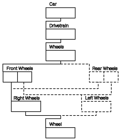
Suppose an operator needs to pick the right-front wheel on a car. Your application defines each part of the car as detectable. In this scenario, the operator picks the right-front wheel. The system supplies your application with a pick path representing the right-wheel's position in the hierarchy. The figure, "Sample Pick Path for Right-Front Wheel," depicts the pick path from the Wheel structure up to the Car structure. In this case, the system reports that the path from the right-front wheel structure to the root structure passes through the following structures:
Notice that the pick path contains six entries, making its depth equal to six. Also, the returned information is in a bottom-up fashion, as specified in the Initialize Pick (GPINPK) subroutine discussed in "Providing Initial Values for a PICK Device" A top-down pick path would have returned the identical pick path information in reverse order.
The graPHIGS API also provides a means of grouping primitives or several primitives with a type of label called a PICK identifier. This enables the application program to keep track of primitives without needing to know their element number.
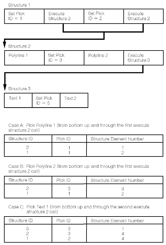
The figure, "Sample Pick Path Information," depicts the returned pick path information. This information includes the:
The Request Pick (GPRQPK) subroutine enables your application to request pick input.
Your application selects an operating mode using the Set Pick Mode (GPPKMO) subroutine. GPPKMO lets your application specify whether the PICK device is in REQUEST , SAMPLE , or EVENT mode. The Operating Mode of each PICK device is set independently. For example, your application might put one PICK device in EVENT mode and another in SAMPLE mode.
Your application initializes the PICK device through the Initialize Pick (GPINPK) subroutine. For example, your application can initialize such things as the pick echo area and the direction in which the pick path is constructed (top-down or bottom-up).
The pick echo area defines the region of the screen within which the PICK device is active. As with other input devices, the pick prompt and echo are clipped to the pick echo area.
A primitive is picked when it intersects a PICK device's pick aperture. In the graPHIGS API, a pick aperture is a rectangular area defined in Device Coordinates (DC) which is attached to the screen cursor.
Input device initialization subroutines may be called only when the device is in REQUEST mode, that is, when the device is not activated.
The subroutine call needed to obtain input from a PICK device depends on the Operating Mode of that device.
In REQUEST mode, your application is responsible for initiating all interactions with the PICK device operator. If your application needs PICK input from an operator before it can proceed, it asks the operator for input by issuing a Request Pick (GPRQPK) subroutine.
After issuing the request, the graPHIGS API waits for the operator to satisfy the request.
As with all PICK input, the returned information contains the status of the pick, the depth of the pick path, and the pick path itself.
After the requested information is obtained, the system returns control to your application so it can resume processing and determine how to use the pick path information.
Setting a PICK device in SAMPLE mode activates the PICK device.
In order to sample a PICK device, your application issues a Sample Pick (GPSMPK) subroutine. After issuing a GPSMPK subroutine, your application receives the input information as fast as the system can supply it. Lacking synchronization, the use of a PICK device in this mode has limited utility.
Setting a PICK device in EVENT mode activates the device and establishes an indirect relationship between your application and a PICK device that is mediated by the event queue.
An operator triggers PICK events which are placed on the event queue. Your application can then get that input from the event queue. This lets operator input and application processing occur asynchronously.
Upon triggering the PICK device, the depth of the pick and pick path data are added to the event queue.
When the PICK event becomes the next event on the queue, your application issues a GPAWEV subroutine call. The graPHIGS API gives your application the identification of the device corresponding to the current event report. If the input came from a PICK device and your application wants to use that input, your application issues a Get Pick (GPGTPK) subroutine call. GPGTPK returns the value of the PICK input.
The graPHIGS API also supports extended pick subroutine calls which are discussed in Part Two of this book.
A STROKE input device provides a sequence of positions in World Coordinate (WC), and the view index whose matrix was used to convert the positions from Device Coordinates (DC) to the World Coordinate System (WCS). For a given sequence of points, the active view of highest priority containing all of those points is used for this conversion. Generally, all STROKE input occurs from View 0, the default highest priority view, unless this relationship is changed. The tablet with stylus is an example of a STROKE input device. A STROKE input value is simply a sequence of location values.
Your application selects an Operating Mode of a STROKE device using the Set Stroke Mode (GPSKMO) subroutine. GPSKMO lets your application specify whether the STROKE device is in REQUEST , SAMPLE , or EVENT mode. It also lets your application define the Operating Mode of each STROKE device, independently. For example, your application might put one STROKE device in EVENT mode and another in SAMPLE mode.
Your application initializes the STROKE device through the Initialize Stroke (GPINSK) subroutine. For example, your application can specify such things as the number of points in the initial stroke, the coordinates of each point in the initial stroke, the type of prompt and echo, and the length of the STROKE input buffer.
The stroke echo area defines the region of the screen within which the STROKE device is active. As with other input devices, the stroke prompt and echo are clipped to the stroke echo area.
GPINSK lets your application provide an initial sequence of STROKE locations. STROKE input values are added to the STROKE buffer beginning at a location specified in the GPINSK subroutine. This location is referred to as the editing position within the STROKE buffer. For example, an editing position of one causes the replacement of the initialized STROKE values beginning at the first point. An editing position of one greater than the number of initial points appends the STROKE input to the initialized values.
The graPHIGS API enables your application to specify the size of the STROKE buffer, which is the maximum number of points allowable for STROKE input. Notice that this may be limited by the maximum buffer size on a given workstation.
STROKE devices have different echo types including:
Input device initialization subroutines may be called only when the device is in REQUEST mode, that is, when the device is not activated.
The subroutine call needed to obtain input from a STROKE device depends on the Operating Mode of that device.
In REQUEST mode, your application is responsible for initiating all interactions with the STROKE device operator. If your application needs STROKE input from an operator before it can proceed, it asks the operator for input by issuing a Request Stroke (GPRQSK) subroutine call.
After issuing the request, the graPHIGS API waits for the operator to satisfy the request.
When the operator triggers the STROKE device, the system sends your application the number of coordinate points in the array, the array containing the points, and the view in which the stroke occurred.
After the requested information is obtained, the system returns control to your application so it can resume processing and determine how to use the returned information.
Setting a STROKE device in SAMPLE mode activates the STROKE device.
In order to sample a STROKE device, your application issues a Sample Stroke (GPSMSK) subroutine call. After issuing a GPSMSK subroutine, your application receives, from the API, the input information as fast as the system can supply it. Lacking synchronization, the use of a STROKE device in this mode has limited utility.
Setting a STROKE device in EVENT mode activates the device and establishes an indirect relationship between your application and a STROKE device that is mediated by the event queue.
An operator triggers STROKE events which are placed on the event queue. Your application can then get that input from the event queue. This lets operator input and application processing occur asynchronously.
When the STROKE event becomes the next event on the queue, your application issues a GPAWEV subroutine call. The graPHIGS API gives your application the identification of the device corresponding to the current event report. If the input came from a STROKE device and your application wants to use that input, your application issues a Get Stroke (GPGTSK) subroutine. GPGTSK returns the value of the STROKE input.
A STRING device allows an operator to input text. The keyboard is an example of a STRING input mechanism. To input a string of characters, the operator presses alphanumeric keys. To trigger a typical STRING device, the operator presses the ENTER key.
Your application selects an Operating Mode using the Set String Mode (GPSTMO) subroutine. GPSTMO lets your application specify whether the STRING device is in REQUEST , SAMPLE , or EVENT mode. It also lets your application define the Operating Mode of each STRING device, independently. For example, your application might put one STRING device in EVENT mode and another in SAMPLE mode.
Your application initializes the STRING device through the Initialize String (GPINST) subroutine. For example, your application can specify such things as the length of an initial string, the text of the initial string and the maximum length of the STRING input buffer.
The string echo is positioned in the lower left corner of the echo area specified in the GPINST subroutine. String echo is clipped to this area.
GPINST lets your application provide an initial string which is placed in the STRING buffer. String input values are added to the string buffer beginning at a location specified in the GPINST subroutine. This position is referred to as the initial cursor position. For example, a cursor position of one causes replacement of the initialized string values, beginning at the first character. A cursor position of one greater than the number of initial characters appends string input to the initialized values.
The graPHIGS API enables your application to specify the size for the STRING input buffer, which is the maximum number of characters allowable for string input. This may be limited by the maximum supported buffer size on a given workstation.
The STRING device echo typically is a string of displayed characters. Notice that your application can prevent the characters from displaying by turning echo OFF.
String Echo Type 2 allows your application to pass a protected prompt string to a STRING device on the Initialize String (GPINST) subroutine. This prompt string is passed in via the data record and is displayed in the lower left corner of the echo area, and is followed by the input buffer echo. The prompt may not be typed over and is not returned with the STRING device input. The initial cursor position is given as an offset in the input buffer. The specified STRING input buffer size, plus the prompt length, must be less than or equal to the maximum STRING input buffer size as defined in the actual WDT.
Input device initialization functions may be called only when the device is in REQUEST mode, that is, when the device is not activated.
The subroutine call needed to obtain input from a STRING device depends on the Operating Mode of that device.
In REQUEST mode, your application is responsible for initiating all interactions with the STRING device operator. If your application needs STRING input from an operator before it can proceed, it asks the operator for input by issuing a Request String (GPRQST) subroutine call.
After issuing the request, the graPHIGS API waits for the operator to satisfy the request. When the operator triggers the STRING device, the system sends your application the length of the string in bytes and the text string. After the requested information is obtained, the system returns control to your application so it can resume processing and determine how to use the returned information.
Setting a STRING device in SAMPLE mode activates the STRING device.
In order to sample a STRING device, your application issues a Sample String (GPSMST) subroutine call. After issuing a GPSMST subroutine, your application receives the string data as fast as the system can supply it. Lacking synchronization, the use of a STRING device in this mode has limited utility.
Setting a STRING device in EVENT mode activates the device and establishes an indirect relationship between your application and a STRING device that is mediated by the event queue.
An operator triggers STRING events which are placed on the event queue. Your application can then get that input from the event queue. This lets operator input and application processing occur asynchronously.
When the STRING event becomes the next event on the queue, your application issues a GPAWEV subroutine. The graPHIGS API gives your application the identification of the device corresponding to the current event report. If the input came from a STRING device and your application wants to use that input, your application issues a Get String (GPGTST) subroutine call. GPGTST returns the value of the STRING input.
A VALUATOR device provides a real number. A dial is an example of a VALUATOR input mechanism. Each dial on the workstation is a separate VALUATOR device. For example, the IBM 5080 can have eight VALUATOR devices.
| Modified Sample Program 1 |
|---|
You can now add a VALUATOR device to the sample program. The VALUATOR will allow you to modify the view matrix of one of the views and provide a zooming effect on the house. Modify the sample program as follows:
|
Modify your sample program, compile it and run it. Try turning dial 1 of the VALUATOR , there should be a zooming effect on the house on the lower left view. Also, the echo of the VALUATOR should be displayed on the lower left corner of the screen.
Your application selects an Operating Mode using the Set Valuator Mode (GPVLMO) subroutine call. GPVLMO lets your application specify whether the VALUATOR device is in REQUEST , SAMPLE , or EVENT mode. It also lets your application define the Operating Mode of each VALUATOR device, independently. If, for example, your application is interacting with a set of dials, the system defines each dial separately. This lets your application set one dial in EVENT mode and another in SAMPLE mode.
In the sample program, the statement:
CALL GPVLMO(WSID,1,3,2)
sets dial 1 to EVENT mode.
Your application initializes the VALUATOR device through the Initialize Valuator (GPINVL) subroutine. For example, your application can specify such things as the VALUATOR 's initial value, its minimum and maximum values, and where the VALUATOR 's echo is placed.
In the sample program, the statement:
CALL GPINVL(WSID,1,1.,4,AREA,LOW,HIGH,VDATAL,VDATA)
initializes dial 1 of the VALUATOR device.
One valuator echo type is a digital display. The digital display changes as the operator moves the valuator. If the VALUATOR device is a dial, your application can specify that one rotation of the dial covers the entire range, or that a number of rotations covers the range. In the sample, the VDATA parameter establishes 10 turns between the LOW and HIGH values. The initial value of the dial is 1.0.
The valuator echo is positioned in the lower left corner of the echo area specified in the GPINVL subroutine call. The valuator echo is clipped to this area.
Input device initialization functions may be called only when the device is in REQUEST mode, that is, when the device is not activated.
The subroutine call needed to obtain input from a VALUATOR device depends on the Operating Mode of that device.
In REQUEST mode, your application is responsible for initiating all interactions with the VALUATOR device operator. If your application needs VALUATOR input from an operator before it can proceed, it asks the operator for input by issuing a Request Valuator (GPRQVL) subroutine.
After issuing the request, the graPHIGS API waits for the operator to satisfy the request.
When the operator triggers the VALUATOR device, the system sends that value to your application.
After the requested information is obtained, the system returns control to your application so it can resume processing and determine how to use the returned information.
Setting a VALUATOR device in SAMPLE mode activates the valuator device.
In order to sample a VALUATOR device, your application issues a Sample Valuator (GPSMVL) subroutine. After issuing a GPSMVL subroutine, your application receives, from the graPHIGS API, the VALUATOR data as fast as the system can supply it.
Note: VALUATORS in EVENT mode typically provide a more efficient communication mechanism with your application.
Setting a VALUATOR device in EVENT mode activates the device and establishes an indirect relationship between your application and a VALUATOR device that is mediated by the event queue.
An operator triggers VALUATOR events which are placed on the event queue. On the IBM 5080 workstation, a VALUATOR event is triggered by dial movement. This means that the application is notified of dial values only when they change. Your application can then get that input from the event queue. This lets operator input and application processing occur asynchronously.
When the VALUATOR event becomes the next event on the queue, your application issues a GPAWEV subroutine call. The graPHIGS API gives your application the identification of the device corresponding to the current event report. If the input came from a VALUATOR device and your application wants to use that input, your application issues a Get Valuator (GPGTVL) subroutine call. GPGTVL returns the value of the VALUATOR input.
In the sample program, the statement:
CALL GPGTVL(VVALUE)
gets the value of dial 1 from the event queue. This value is then used to initialize the scaling vector which in turn is used to determine the view matrix VMATRX for the zooming effect. The matrix is calculated using the utility function GPSC2 The GPXVR subroutine is then used to assign VMATRX to view 1 of the WSID workstation. An update workstation operation is then needed.