This chapter provides information to help you take advantage of the graPHIGS API's advanced input and event handling capabilities. It contains a discussion of logical and physical input devices, input device triggers, cursor shape control, and extensions to the PHIGS input model. A short review of the PHIGS input model will be presented followed by a discussion of the advanced graPHIGS API functions. If you are unfamiliar with using the graPHIGS API to obtain input, see Chapter 7. "Input Devices" located in the first part of this book.
This section contains a short overview of the PHIGS input device model. Later portions of this chapter will discuss the graPHIGS API extensions to the model that provide you with greater control over input processing.
In order to promote application portability, the PHIGS standard adopted the concept of logical input devices. The logical input device model shields your application programs from differences in hardware input capabilities by providing a consistent method of acquiring input.
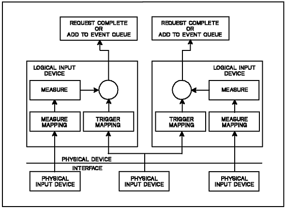
Each logical input device has the concept of a measure The measure is a value determined by one or more physical input devices together with a measure mapping The measure reflects the current state of the logical input value and is continuously updated while the logical input device is active.
The PHIGS standard defines six logical input device classes. A class is defined by the measure returned by the device as described below:
The logical input device model also includes the concept of triggers. A trigger is used to indicate a significant point in time when an operation is to be performed on the measure or the state of the logical input device. The logical input device model is illustrated in the figure, "PHIGS Input Device Model." Input triggers are discussed in detail later in this chapter.
In addition to the measure and trigger, a logical input device may generate output to indicate the current state of the device's measure or to acknowledge the receipt of a trigger. This output is usually visible or audible and is called the input device ECHO
As discussed in the first part of this book (Basic), the method of obtaining the measure of a device depends upon the device's Operating Mode. The three modes defined by the PHIGS standard are 1=REQUEST , 2=SAMPLE , and 3=EVENT as defined in the following sections.
An input device in REQUEST mode is inactive until your application program specifically requests input from the device. Control will not return to your application program until the request is satisfied by the user triggering the device.
When an input device is in SAMPLE mode the device is active meaning that it is ready to provide input. To obtain the input, your application program samples the device's current measure. The most common use of SAMPLE mode input is to determine the current measure of a LOCATOR or VALUATOR device. Other devices have limited utility in SAMPLE mode.
Like a device in SAMPLE mode, a device in EVENT mode is active but, instead of your application program sampling the device for input, the user triggers the device to generate the input. Because you can trigger the device at any time, the input is placed in an event queue to be processed when your application program is ready. EVENT mode input allows you to input data even if your application is busy doing something else.
To determine if an event has occurred your application calls the Await Event (GPAWEV) subroutine. If the event queue is empty, GPAWEV will wait for a specified number of seconds for an event to occur. If an event occurs during the wait or there is an event on the queue when GPAWEV is called, GPAWEV will return the following information:
If the wait time elapses, the event class will be 0=NONE
In the PHIGS standard, only input devices can generate events. Therefore, the major code is defined as the workstation identifier, the event class is the input device class, and the minor code is the input device number. If the event class is not 0=NONE , your application can retrieve the event information from the current event report, using one of the graPHIGS API get event subroutine calls. For example, if the event class returned by GPAWEV indicates that the event was generated by a choice device (class = 4), your application would call the Get Choice (GPGTCH) subroutine to get the choice information from the event queue.
The concept of events has been extended in the graPHIGS API to define events that are not related to input devices as discussed in the following section.
In addition to input device events, the graPHIGS API can also generate and process events which are not related to input devices. This section describes each of those events, how they are generated, and how your application can use them. All events are categorized by the event class parameter of the Await Event (GPAWEV) subroutine as listed below:
This class is currently used to notify your application that the 5080 link switch is switched away from your application and therefore no graPHIGS API subroutines should be directed to that 5080. This event also indicates that a workstation which is realized as a virtual workstation is disconnected from the actual hardware workstation. The major code contains the workstation's identifier but the minor code is not set.
This class is currently used to notify your application that the 5080 link switch is switched back to the application but, since the state of the 5080 is not known, the workstation should be closed, reopened, and reinitialized. The event is also used to indicate that a workstation realized as a virtual workstation has been reconnected to the actual hardware workstation. The major code contains the workstation's identifier but the minor code is not set.
High function workstations can update their display surface without forcing your application to wait for the update to complete. When your application calls an Update Workstation (GPUPWS) or Redraw All Structures (GPRAST) subroutine, the graPHIGS APIwill initiate the update and return control to your application. Some time later the update will be complete.
An event of this class is generated when an update completion notification has been requested using the Set Shell Deferral State (GPSHDF) subroutine and the graPHIGS APInucleus has completed the processing of a previously invoked GPUPWS or GPRAST The major code contains the workstation identifier and the minor code contains the display status.
This event class is returned when the size of a group of simultaneous events exceeds the input buffer size that is being used by the nucleus for sending events from the nucleus to the shell. The major code will contain the workstation identifier and the minor code is undefined.
This class is returned when the user changes the size of an X-Window containing the output of a X-Window-type workstation. The major code contains the workstation identifier and the minor code is undefined. In order to receive this event, you must enable notification using the escape (GPES) subroutine with function 1009. After receiving a resize notification event, your application can use the Inquire Mapped Display Surface Size (GPQMDS) subroutine to obtain the size of the mapped display surface. (The mapped display surface is the subarea of the X-Window that the workstation uses as the display surface for graphics output.) Note that the display surface size returned by Inquire Maximum Display Surface Size (GPQDS) and Inquire Maximum Display Surface Size (GPQADS), does not change as the window is resized. You can specify the aspect ratio of the display surface in the X-Window by using the XWINDASP PROCOPT.
The following class values are defined for application messages:
This class shows that an application message event was generated by another application process using the Send Broadcast Message (GPSBMS) subroutine. The major and minor codes and event data are set to the values specified by the other application process.
This class shows that an application message event was generated by another application process using the Send Private Message (GPSPMS) subroutine. The major and minor codes and event data are set to the values specified by the other application process.
With the introduction of application message events, the maximum size of events and the number of events that the queue should hold will be more application specific. Therefore, your application may now define the size of the event queue through the External Defaults File (EDF) or through the Application Defaults Interface Block (ADIB) parameter of the Open graPHIGS subroutine. ADIBs and EDFs are discussed in detail in The graPHIGS Programming Interface: Technical Reference
For more information on the use of application messages, see Chapter 10. "Advanced Concepts"
In order to prevent loss of data due to out-of-memory errors on a graPHIGS API nucleus, a "threshold exceeded" event is supported. The event is generated whenever the storage allocated to a structure store exceeds a specified threshold value. The structure store threshold value is set using the Set Structure Store Threshold (GPSSTH) subroutine. The event will only be generated once per setting.
The event major code contains the structure store identifier that caused the event and the minor code contains the threshold value that was exceeded.
Some applications require greater control over how events are processed. To accommodate that need, the graPHIGS API permits your application to specify an event handling function through the Define Event Handling Function (GPEVHN) subroutine. GPEVHN takes the following two parameters:
| Parameter | Description |
| handler | the address of your application defined event handler |
| anchor | a pointer to an anchor block defined by yourapplication. |
Whenever an event occurs, your event handler will be called by the graPHIGS API and passed the following parameters by reference using the operating system's standard calling convention:
| Parameter | Description |
| anchor | your application anchor block specified in the call to GPEVHN |
| major | the major code of the event |
| class | the class of the event |
| minor | the minor code of the event |
| length | the length of the event data |
| data | the event data |
| sflag | an event status flag indicating the following:
|
| rflag | a return flag which your event handler should set to indicate whether or not the event should be queued or discarded. |
Event handlers are subject to the following restrictions:
With the stated restrictions, the function of most event handlers should be limited to the following:
The phrase "physical input device" refers to the actual hardware device used to implement a logical input device as shown in the figure, "PHIGS Input Device Model." For example, a computer keyboard is a physical input device used to implement a logical string input device.
In order to meet the needs of application programmers, the graPHIGS API extends the PHIGS input model to allow your application program to map additional physical input devices to the PHIGS logical input devices as described in the following sections.
Each physical device is categorized by the type of input it provides. The currently defined categories are 1=BUTTON , 2=SCALAR , and 3=2D_VECTOR as discussed below:
A device in the BUTTON category will provide a discrete integer value when some transition of the physical device takes place such as when a key on a keyboard is depressed. The set of integer values that a device may return are not required to lie within one contiguous range. This device is further characterized by the list of all possible integers that it may return. This would correspond to the keys on a keyboard for example. If a device can detect make and break transitions, then distinct integer values are provided for each.
A SCALAR device will provide an integer within a single range. A specific SCALAR physical device may return either absolute or relative values. For an absolute device, the limits of the range are the devices' physical limits (minimum and maximum value that the device can input). For a relative device, there is no minimum value so a value of zero is used. The maximum value of the range represents the number of increments of physical motion. A unit of physical motion is different for different physical devices. For example, for a dial device, one unit of physical motion equals one turn of the dial. These values will in reality be related to the operation of the corresponding logical input device. The physical input is mapped to the range of input values that the logical device can input as specified by the application on the initialize device subroutine call.
A 2D_VECTOR device is similar to a SCALAR device except that two integer values are generated by the device instead of one. It is often used to control the cursor displayed on the screen. The device can provide either relative or absolute values. A mouse is an example of a 2D_VECTOR device that would return relative values, while a tablet is a 2D_VECTOR device that would return absolute values. For an absolute device, the limits of the range are the devices' physical limits. The minimum and maximum values generally correspond to the edges of the screen in the case of a device connected to the graphics cursor. For a relative device, there is no minimum limit so a value of zero is used. The maximum value of the range represents the number of increments of one unit of physical motion. For a mouse physical device, one unit of physical motion equals the amount of motion necessary to move the cursor from one edge of the screen to its opposite edge. The limits of the range, as with SCALAR devices, are mapped to the range that the corresponding logical device can input as specified by the application on the initialize device subroutine call.
Notes:
Some applications require the use of physical input devices other than those defined and explicitly supported by the graPHIGS API In order to meet that requirement and still isolate your application from the characteristics of a physical device and provide the measure mapping operations of logical input devices, the graPHIGS API allows your application to logically and physically detach the default set of physical devices and emulate them instead.
For example, the IBM digitizer is a physical device which may be accessed directly by your application. Tailoring this device to the task the end user is performing will give you desirable results. One possibility is to use a section of the digitizer to emulate the normal operation of the tablet by providing the user with a way to switch between using the tablet or a section of the digitizer as the physical device that is driving the PICK , LOCATOR , and STROKE logical devices. This would allow the user the convenience of using these logical devices from either the tablet or digitizer.
The graPHIGS API cannot provide the same level of functions that your application can by accessing the digitizer directly. Even if the graPHIGS API were to perform the tablet emulation described above, most applications would still require access to the unique characteristics of the digitizer such as control over granularity, access to puck keys, lights, and audible alarms.
This same argument applies to other IBM and non-IBM devices which you may choose to use. Each physical device has many different characteristics and it would be impractical for the graPHIGS API to support every one.
To allow your application to replace and emulate a physical device, the graPHIGS API provides the Set Physical Device Mode (GPPDMO) subroutine. The parameters for this subroutine include the physical device category, identifier, and mode. The mode may be specified as either 1=DISABLED or 2=ENABLED When DISABLED , the physical device will not generate any input to the logical input devices to which it is normally connected. ENABLED is the default mode that permits the physical device to drive the logical devices. When a physical device is disabled, your application may emulate it using the Emulate Physical Device (GPEPD) subroutine. The parameters of GPEPD are defined as follows:
| Parameter | Description |
| wsid | workstation identifier of the device to be emulated |
| category | physical device category (1=BUTTON , 2=SCALAR , or 3=2D_VECTOR ) |
| device | physical device identifier |
| value | emulated input value(s) to be passed to the logical input device(s). |
The simulated input will be passed to the set of logical input devices that are connected to the specified physical device. If the specified input values do not fall within the range normally generated by the physical device or the physical device does not exist, an error will be generated. The normal operation of the logical input device is unchanged.
The characteristics of a physical input device can be determined with the Inquire Physical Device Characteristics (GPQPDC) subroutine. The input parameters to GPQPDC are the physical device category and a physical device identifier. GPQPDC returns information which is dependent on the category of the physical device.
In Version 1 of the graPHIGS API, logical input devices were not available to your application if the required physical input devices were not present. With the introduction of physical input device emulation, there are cases where your application may require emulation of physical devices that are not really present. Therefore, a new defaults option has been defined that allows your application to control whether or not logical input devices are created even if the corresponding physical devices are not present. This option is specified as a 'procopt' in either an External Defaults File (EDF) or through a parameter of the Create Workstation (GPCRWS) subroutine. When logical devices are specified unconditional upon creation, your application must use the Inquire Physical Device Characteristics (GPQPDC) subroutine to determine if the physical device is actually present.
Each logical input device may have one or more trigger levels with one trigger each. Each trigger level corresponds to an atomic operation on the measure or state of an input device.
The first or primarytrigger level causes the logical input device to pass its current measure value back to your application or to add the measure to the event queue depending on the mode of the logical input device. Every logical input device has a primary trigger.
Trigger levels greater than the first
(secondary) are used to change the measure or the
state of the logical input device.
As an example, the following table summarizes the secondary
triggers for the STROKE
and PICK
logical input devices
supported by the 5080 workstation type:
Table: 5080 Secondary Trigger Levels
| Device | Trigger Levels |
|---|---|
| STROKE #1 |
|
| STROKE #2 |
|
| PICK #1 |
|
A trigger for any level can be generated by one or more physical input devices in conjunction with a trigger mapping A trigger only affects a logical input device that is in EVENT mode or has a REQUEST pending. Triggers at any other time have no effect on the logical input device.
The relationship between the physical and logical input
devices is determined by the workstation developer and
cannot be altered.
For example, the following table lists the physical input
devices and the logical input device measure and trigger
processes which use them:
Table: 5080 Physical/Logical Device
Correspondence
| Physical Device | Logical Device Measure |
Logical Device Trigger |
|---|---|---|
| Tablet | LOCATOR 1,2 STROKE 1,2 PICK 1 |
|
| Puck or Stylus | CHOICE 2 | LOCATOR 1,2 STROKE 1,2 VALUATOR 1-8 PICK 1 STRING 1-16 |
| LPFK | CHOICE 1 | LOCATOR 1,2 STROKE 1,2 VALUATOR 1-8 PICK 1 STRING 1-16 |
| Keyboard | CHOICE 3 CHOICE 4 STRING 1-16 |
LOCATOR 1,2 STROKE 1,2 VALUATOR 1-8 PICK 1 STRING 1-16 |
| Dial 1 | VALUATOR 1 | VALUATOR 1 |
| Dial 2 | VALUATOR 2 | VALUATOR 2 |
| Dial 3 | VALUATOR 3 | VALUATOR 3 |
| Dial 4 | VALUATOR 4 | VALUATOR 4 |
| Dial 5 | VALUATOR 5 | VALUATOR 5 |
| Dial 6 | VALUATOR 6 | VALUATOR 6 |
| Dial 7 | VALUATOR 7 | VALUATOR 7 |
| Dial 8 | VALUATOR 8 | VALUATOR 8 |
Each logical input device has a set of BUTTON physical devices which are used to trigger any of the logical device's trigger levels. Since a BUTTON physical device can generate many values, the trigger mapping for each logical input device acts as a filter on these values so that only a subset will actually trigger the logical device.
The programmable trigger concept allows your application to modify the trigger mapping by selecting which buttons on a physical BUTTON device will trigger each of the trigger levels of the logical device. A trigger mapping includes the following information:
| Trigger Type | A trigger type value greater than zero represents a physical device identifier from the BUTTON category that is to be used to generate the trigger. Values less than zero are reserved for triggers not generated by physical devices. |
| Trigger Qualifier | A trigger qualifier defines which values from the physical BUTTON device will trigger the specified trigger level. These values may be specified as ranges for convenience. |
The list of BUTTON type physical devices that may be used for triggering a specific logical input device can be determined using the Inquire Input Trigger Capabilities (GPQIT) subroutine. This subroutine defines the correspondence between the physical devices and the triggers of the logical input devices.
Some national languages such as Japanese allow the user to enter a pre-editing mode or to view pop-up translation menus (auxiliary windows) while typing in a string device. In these modes, characters are interpreted by a special language processor (the Input Method for AIX), before they are entered into the graPHIGS string device.
Triggers behave as follows during pre-editing mode and when auxiliary windows are present:
Programmable triggers have been extended to include the notion of firing the primary trigger when the physical measure changes. The change in measure trigger allows your application to follow the motion the mouse or tablet puck as it moves. This is a very common mode of operation. For example, your application may use the cursor to input values for a transformation matrix based on cursor's XY screen location. This type of trigger has always been used for the VALUATOR devices in EVENT mode but was not exposed since the VALUATOR does not have programmable triggers.
The change in measure trigger is set by the Set Input Device Trigger (GPIT) subroutine where the trigger type parameter is -1 and is only valid for the primary trigger level of a logical input device.
The low trigger threshold qualifier specifies the minimum change, in 2D_VECTOR physical device units, needed for triggering. Use GPQPDC to determine the valid ranges for the 2D_VECTOR devices. The high trigger qualifier is not used for this trigger type and must be set to 0.
For PICK devices, the graPHIGS API accumulates the distance from one event to the next and correlates only when the low qualifier threshold is exceeded, except for the last event occurring in a chain of events. The last in a chain of events is always correlated, regardless of the low qualifier. Events accumulated prior to the last event are also correlated when they exceed the low qualifier threshold.
This trigger type can be interpreted as an option for the trigger mapping process of the logical input device. When this trigger type is used, the trigger mapping process monitors the physical measure for change and when the cumulative change is more than the value contained in the low trigger qualifier, the primary trigger is fired.
Use the Inquire Input Trigger Capabilities (GPQIT) subroutine to determine whether an input device supports this trigger type.
Note: The graPHIGS API does not limit the change in measure trigger type to use by Distributed Application Processes (DAPs) but the communications overhead will be high if the program receiving the events does not reside in the same node as the one to which the user's display is directly attached.
The trigger when primary fires mode allows the secondary trigger to correspond to the same event as the primary trigger. Trigger when primary fires is set by the Set Input Device Trigger (GPIT) subroutine where the trigger type parameter is -2 and is only valid for the secondary trigger level of a logical input device. The low and high trigger qualifiers have no meaning and must be set to 0.
When used in combination, trigger by measure (trigger type -1), and trigger when primary fires (trigger type -2), implement a sliding pick device that returns an event for the first primitive crossed if correlation is set to ON trigger by measure should be set to a small value to avoid skipping primitives.
Input Device Dependent Triggers are used by some logical input devices as a default trigger type because the input device uses a special type of trigger or one which is mode dependent. A VALUATOR input device on the 5080 workstation is a good example of this. On a 5080 workstation the enter key is the primary trigger for VALUATOR devices in REQUEST mode but movement is the primary trigger in EVENT mode. The default trigger for a VALUATOR is "logical input device dependent" to allow workstations to support programmable triggers without returning ambiguous or incorrect information on inquiry subroutines. The Input Device Dependent Trigger type is only returned from inquiry subroutine and is never valid as a parameter to a trigger setting subroutine call.
On several of the workstations supported by the graPHIGS API, the graphics cursor is used as the prompt for LOCATOR , STROKE , and PICK input devices. Each one of the logical input devices has a different prompt shape. The LOCATOR uses a "+" shape, the STROKE uses an "X" and the PICK device uses a box whose size corresponds to the current pick aperture. The prompt is only displayed when the device is active and the cursor is in the input device's ECHO area. Since ECHO areas may partially overlay each other, the shape of the cursor may change as it is moved around the screen passing through different combinations of active ECHO areas.
The cursor is drawn by display adapter hardware in some configurations. This produces cursor movement performance that is independent of screen content. Many application developers like to define their own cursor shapes. Two workstation subroutines are provided to accomplish this. The Set Cursor Shape (GPCUS) subroutine selects the cursor shape for a specified workstation. The second parameter of GPCUS is an index which selects either a specific type of cursor, such as a cross hair, or an entry in the workstation's cursor shape table. GPCUS also allows the selection of a two-color (XOR echo) representation of any of the workstation cursors, as well as an option to disable the graPHIGS API cursors and allow the application to use the default cursor facilities native to a window system such as those provided by X-Windows. (See HWCURS PROCOPT for information on using the hardware crosshair cursor.) Use the Set Cursor Representation (GPCUR) subroutine to redefine an entry in the workstation's cursor shape table. When an entry is selected, that cursor shape is used for all logical input devices that require a graphics cursor. The cursor shape, therefore, is not unique to the logical input device nor does it change as the cursor moves around the screen unless it moves outside the echo area or the application changes it. GPCUR takes the following parameters:
The size of the cursor shape table and the cursor formats that are supported by a workstation can be determined through the Inquire Cursor Facilities (GPQCUF) subroutine. The only cursor format currently defined requires a two-dimensional array of pixel values with 1 bit per pixel. For this format, the cursor definition must contain the following:
Note: For this format, the specified array sizes must match the maximum size pixel array which can be inquired using GPQCUF
Based on the organization of your graphics data and performance considerations, you may choose to have the graPHIGS API return the FIRST or LAST primitive which is detected by a PICK device. In addition, some application programmers would like their applications to receive every primitive that passes through the PICK aperture. This allows your application or the user to make the decision as to which primitive of those passing through the PICK aperture is the actual target of the operation. You may also choose to perform some operations on every primitive which passes through the PICK aperture.
The pick selection criteria controls whether the FIRST , LAST or ALL primitives passing through the PICK aperture are returned to your application. This characteristic of a PICK device can be initialized through the Set Pick Selection Criteria (GPPKSC) escape subroutine. One of the parameters passed to GPPKSC controls whether or not the pick selection criteria is FIRST , LAST , or ALL For selection criteria ALL , every primitive which intersects the PICK aperture will be echoed when pick echoing is ON
If the Pick Selection Criteria is set to ALL and a REQUEST or SAMPLE function is invoked for the PICK device, only information about the FIRST pick primitive will be returned. When the PICK device is in EVENT mode, the list of picked primitives will be returned as simultaneous events. Each event will only contain the information for a single primitive. Several locations on the same curve or surface may lie within the PICK aperture. Each primitive will be returned only once, even if the selection criteria is set to ALL
In addition to controlling the picked primitive using the FIRST , LAST , and ALL order of processing, your application can control the picking of primitives effected by HLHSR processing. The criteria FIRST_VISIBLE , LAST_VISIBLE , and ALL_VISIBLE refer to those primitives that are in the PICK aperture and are visible based on the HLHSR processing. The criteria FIRST , LAST , and ALL refer to those primitives that are in the PICK aperture but not necessarily visible based on HLHSR processing. Any effect due to HLHSR processing does not change which object is picked (i.e., the selected object may not be displayed when HLHSR is active). If a workstation does not support HLHSR processing, then the visible PICK modes operate the same as normal PICK modes.
PICK correlation is the process of determining which graphical elements are intersected by a PICK device's aperture. Typically, correlation is turned on when the user causes a secondary trigger to fire by pressing and holding down a mouse, stylus, or puck button. Releasing the button causes the PICK device's primary trigger to fire and the PICK measure to be sent to your application. Some applications developers however, always want PICK correlation turned ON
By default, the graPHIGS API defines PICK correlation to be OFF when a PICK device is activated. If you want correlation always ON then the PICK device triggers must be set so that correlation is turned ON by any trigger and only turned OFF if the device is put in REQUEST mode (deactivated). This is not convenient since the user must fire a trigger (press a button) to start the correlation process each time the PICK device is activated.
To alleviate this inconvenience the Set Initial Pick Correlation State (GPIPKC) escape subroutine is defined. GPIPKC takes the following three parameters:
| Parameter | Description |
| wsid | the workstation identifier of the PICK device whose correlation state is to be changed |
| device | the PICK device identifier of the PICK device whose correlation state is to be changed |
| state | the Pick Correlation State (1=OFF or 2=ON ). |
A Pick Correlation State of ON specifies that when the device is activated, correlation will be turned on immediately. The default value of OFF specifies that correlation will start when the PICK device's secondary trigger is fired.
Some applications require more information about a picked primitive than a standard PICK device will return. For example, an application may require the view identifier of the picked primitive. Therefore, the PICK device measure has been extended in the graPHIGS API to include the following information:
The extended PICK information is returned by the Get Extended Pick (GPGTXP), Request Extended Pick (GPRQXP), and Sample Extended Pick (GPSMXP) subroutines. If any of the existing pick input subroutines (Get Pick (GPGTPK), Request Pick (GPRQPK), and Sample Pick (GPSMPK)) are issued to a PICK device which returns extended information, only the current pick path without labels will be returned.
Some workstation platforms do not support the extended PICK class. Therefore, to determine if a workstation supports extended PICK , use the Inquire Pick Measure Type (GPQPKT) subroutine. If one of the extended PICK input subroutines is called for a device which does not return extended PICK information, the subroutine call will be rejected with an error.