A POWER or PowerPC microprocessor contains the sequencing and processing controls for instruction fetch, instruction execution, and interrupt action, and implements the instruction set, storage model, and other facilities defined in the POWER and PowerPC architectures.
The processor can execute three classes of instructions:
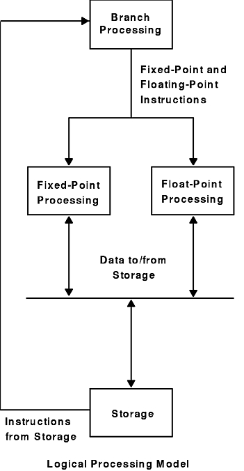
A POWER or PowerPC microprocessor contains a branch processor, a fixed-point processor, and a floating-point processor.
The following figure is a logical representation of instruction processing for POWER and PowerPC.
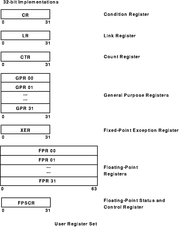
The following figure shows the registers for the PowerPC user instruction set architecture.
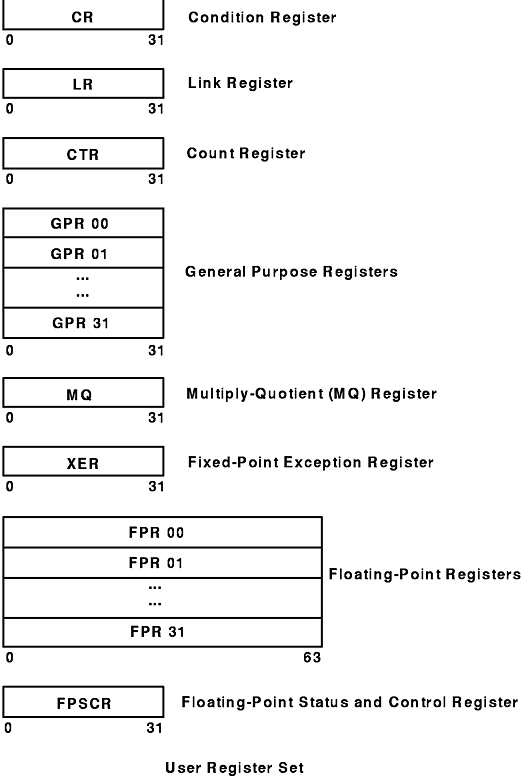
The following figure shows the registers of the POWER user instruction set architecture.
The processing unit is a word-oriented, fixed-point processor functioning in tandem with a doubleword-oriented, floating-point processor. The microprocessor uses 32-bit word-aligned instructions. It provides for byte, halfword, and word operand fetches and stores for fixed point, and word and doubleword operand fetches and stores for floating point. These fetches and stores can occur between main storage and a set of 32 general-purpose registers, and between main storage and a set of 32 floating-point registers.
All instructions are four bytes long and are word-aligned. Therefore, when the processor fetches instructions (for example, branch instructions), the two low-order bits are ignored. Similarly, when the processor develops an instruction address, the two low-order bits of the address are 0.
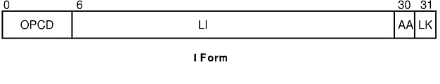
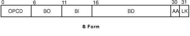
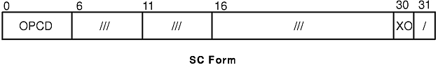
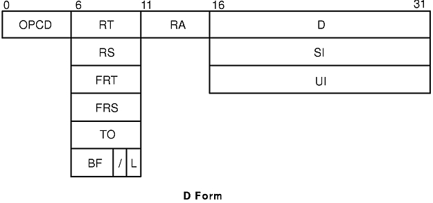
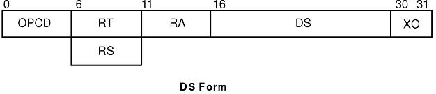
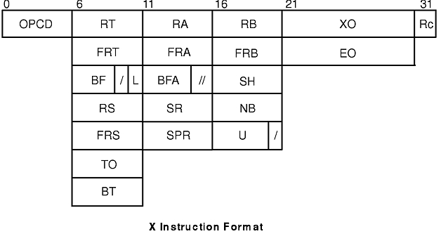
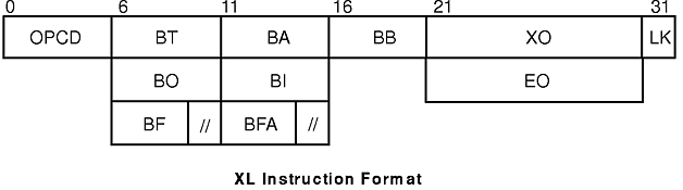
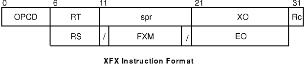
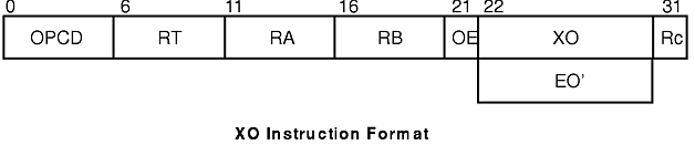
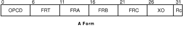
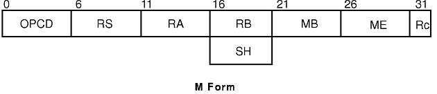
Bits 0-5 always specify the op code. Many instructions also have an extended op code (for example, XO-form instructions). The remaining bits of the instruction contain one or more fields. The alternative fields for the various instruction forms are shown in the following figures:
For some instructions, an instruction field is reserved or must contain a particular value. This is not indicated in the previous figures, but is shown in the syntax for instructions in which these conditions are required. If a reserved field does not have all bits set to 0, or if a field that must contain a particular value does not contain that value, the instruction form is invalid. See "Detection of New Error Conditions" for more information on invalid instruction forms.
In some cases an instruction field occupies more than one contiguous sequence of bits, or occupies a contiguous sequence of bits that are used in permuted order. Such a field is called a split field. In the previous figures and in the syntax for individual instructions, the name of a split field is shown in lowercase letters, once for each of the contiguous bit sequences. In the description of an instruction with a split field, and in certain other places where the individual bits of a split field are identified, the name of the field in lowercase letters represents the concatenation of the sequences from left to right. In all other cases, the name of the field is capitalized and represents the concatenation of the sequences in some order, which does not have to be left to right. The order is described for each affected instruction.
| AA (30) | Specifies an Absolute Address bit: | ||||||||||||
| BA (11:15) | Specifies a bit in the Condition Register (CR) to be used as a source. | ||||||||||||
| BB (16:20) | Specifies a bit in the CR to be used as a source. | ||||||||||||
| BD (16:29) | Specifies a 14-bit signed two's-complement branch displacement that is concatenated on the right with 0b00 and sign-extended to 64 bits (PowerPC) or 32 bits (POWER). This is an immediate field. | ||||||||||||
| BF (6:8) | Specifies one of the CR fields or one of the Floating-Point Status and Control Register (FPSCR) fields as a target. For POWER, if i=BF(6:8), then the i field refers to bits i*4 to (i*4)+3 of the register. | ||||||||||||
| BFA (11:13) | Specifies one of the CR fields or one of the FPSCR fields as a source. For POWER, if j=BFA(11:13), then the j field refers to bits j*4 to (j*4)+3 of the register. | ||||||||||||
| BI (11:15) | Specifies a bit in the CR to be used as the condition of a branch conditional instruction. | ||||||||||||
| BO (6:10) | Specifies options for the branch conditional instructions. The possible encodings for the BO field are: | ||||||||||||
| BT (6:10) | Specifies a bit in the CR or in the FPSCR as the target for the result of an instruction. | ||||||||||||
| D (16:31) | Specifies a 16-bit signed two's-complement integer that is sign-extended to 64 bits (PowerPC) or 32 bits (POWER). This is an immediate field. | ||||||||||||
| EO (21:30) | Specifies a10-bit extended op code used in X-form instructions. | ||||||||||||
| EO' (22:30) | Specifies a 9-bit extended op code used in XO-form instructions. | ||||||||||||
| FL1 (16:19) | Specifies a 4-bit field in the svc (Supervisor Call) instruction. | ||||||||||||
| FL2 (27:29) | Specifies a 3-bit field in the svc instruction. | ||||||||||||
| FLM (7:14) | Specifies a field mask that specifies the FPSCR fields which are to be updated by the mtfsf instruction: | ||||||||||||
| FRA (11:15) | Specifies a floating-point register (FPR) as a source of an operation. | ||||||||||||
| FRB (16:20) | Specifies an FPR as a source of an operation. | ||||||||||||
| FRC (21:25) | Specifies an FPR as a source of an operation. | ||||||||||||
| FRS (6:10) | Specifies an FPR as a source of an operation. | ||||||||||||
| FRT (6:10) | Specifies an FPR as the target of an operation. | ||||||||||||
| FXM (12:19) | Specifies a field mask that specifies the CR fields that are to be updated by the mtcrf instruction: | ||||||||||||
| I (16:19) | Specifies the data to be placed into a field in the FPSCR. This is an immediate field. | ||||||||||||
| LEV (20:26) | This is an immediate field in the svc instruction that addresses the svc routine by b'1' || LEV || b'00000 if the SA field is equal to 0. | ||||||||||||
| LI (6:29) | Specifies a 24-bit signed two's-complement integer that is concatenated on the right with 0b00 and sign-extended to 64 bits (PowerPC) or 32 bits (POWER). This is an immediate field. | ||||||||||||
| LK (31) | Link bit:
| ||||||||||||
| MB (21:25) and ME (26:30) | (POWER) Specifies a 32-bit string. This string consists of a substring of ones surrounded by zeros, or a substring of zeros surrounded by ones. The encoding is:
Let mstart=MB and mstop=ME: If mstart < mstop + 1 then mask(mstart..mstop) = ones mask(all other) = zeros If mstart = mstop + 1 then mask(0:31) = ones If mstart > mstop + 1 then mask(mstop+1..mstart-1) = zeros mask(all other) = ones | ||||||||||||
| NB (16:20) | Specifies the number of bytes to move in an immediate string load or store. | ||||||||||||
| OPCD (0:5) | Primary op code field. | ||||||||||||
| OE (21) | Enables setting the OV and SO fields in the XER for extended arithmetic. | ||||||||||||
| RA (11:15) | Specifies a general-purpose register (GPR) to be used as a source or target. | ||||||||||||
| RB (16:20) | Specifies a GPR to be used as a source. | ||||||||||||
| Rc (31) | Record bit: | ||||||||||||
| RS (6:10) | Specifies a GPR to be used as a source. | ||||||||||||
| RT (6:10) | Specifies a GPR to be used as a target. | ||||||||||||
| SA (30) | SVC Absolute:
| ||||||||||||
| SH (16:20) | Specifies a shift amount. | ||||||||||||
| SI (16:31) | Specifies a 16-bit signed integer. This is an immediate field. | ||||||||||||
| SPR (11:20) | Specifies an SPR for the mtspr and mfspr instructions. See the mtspr and mfspr instructions for information on the SPR encodings. | ||||||||||||
| SR (11:15) | Specifies one of the 16 Segment Registers. Bit 11 is ignored. | ||||||||||||
| TO (6:10) | Specifies the conditions on which to trap. See "Fixed-Point Trap Instructions" for more information on condition encodings.
| ||||||||||||
| U (16:19) | Used as the data to be placed into the FPSCR. This is an immediate field. | ||||||||||||
| UI (16:31) | Specifies a 16-bit unsigned integer. This is an immediate field. | ||||||||||||
| XO (21:30, 22:30, 26:30, or 30) | Extended op code field. |
Processing and Storage: Overview.
PowerPC Architecture.