Most of these steps apply to the Structure Functional Design, Ship Structure Detail Design, and Structure Design applications. Certain steps, where indicated, apply to just one or two of the applications.
An endcut is a closed surface or a volume that will be subtracted from the profile (shape/stiffener). This closed surface (or volume) is modeled using a user defined feature (UDF). Both the Wireframe and Surface Design and Generative Shape Design workbenches can be used to create the endcut geometry.
A GSO license is required if volumes are used to define the endcut geometry.
Starter models are provided to help in the creation of new endcuts. These templates are located in the following folder:
../OS/startup/EquipmentAndSystems/Structure/DetailingFeatures/UDFTemplates
For more information and additional guidelines for defining geometry, see Defining Support Geometry.
For organizational purposes, it is recommended that you create all the features used to design the endcut geometry under a geometrical set called UDF Definition.
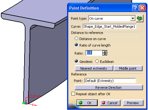
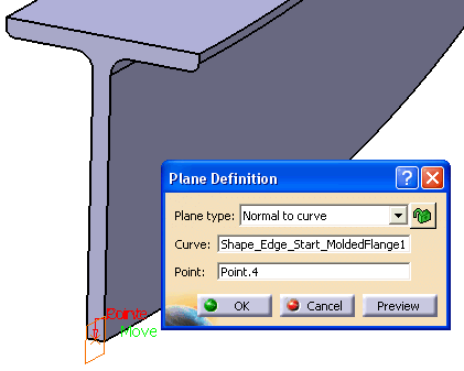
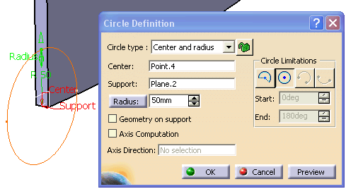
Select the circle as profile and the plane as direction.
-
Create a surface from the circle using the Fill
 command.
 - Extrude this
surface using the Extrude
 command.
The result is a closed surface that can be used to define an endcut.
Naming Conventions for Section Characteristics
When you define your endcut UDF, follow these naming conventions:
- Shape_Face_MoldedFlange1
Shape_Edge_Start_MoldedFlange2
For a contextual endcut, inputs corresponding to the context have an index in there names. For example:
- Shape1_Face_MoldedFlange1
Shape1_Edge_Start_MoldedFlange2
For more information on naming conventions, see Defining Support Geometry.
Creating the Endcut UDF
The Userfeature Definition dialog box opens.
Give the endcut UDF a meaningful name. This is the name the user will see when he instantiates the endcut in his design.
Select UDF Definition in the specifications tree.
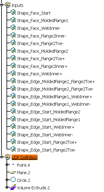
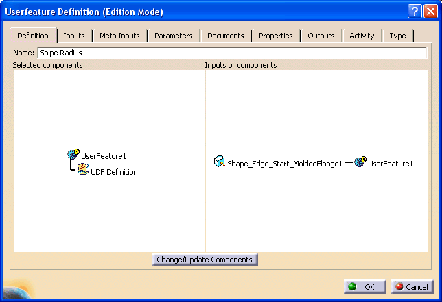
Select the Inputs tab on the Userfeature Definition dialog box.
If the starter model has been used, all the inputs should follow the naming convention.
As shown above, our UDF has only one input: an edge named Shape_Edge_Start_MoldedFlange1.

NOTE: Only published parameters will be accessible when using this endcut.
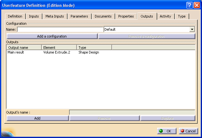
Click OK when done.

Creating the Catalog Selection Preview Image
Follow these steps to create a preview image that is representative of the actual endcut.
- Use the Part Design
workbench and select the Pocket command.
Create a Pocket in the PartBody by selecting the circle. Apply the standard isometric view to your document. Place all 3-D construction geometry in No-Show, then save the document.
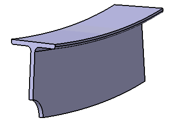
It should look like this:
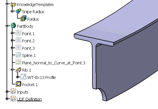
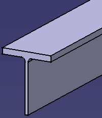
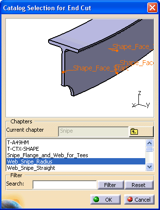
In the Structure Design application, when you place this endcut, the preview in the Catalog Selection for End Cut dialog box looks like this:
Creating a Bitmap Image
You must create an image for each new endcut. The image must be a bitmap file (120 pixels wide by 160 pixels high) to properly fit in the frame of the user interface. It should clearly show the geometry so the user can select the correct detail. It should also clarify the parameters. The image name must match the UDF name.
The location where these bitmap files are stored is defined by a specific PRM resource. This resource is described in List of PRM Resources.
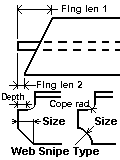
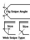
Sample bitmaps, like the ones below, are provided with the product.
![]()

