A user defined feature (UDF) is an object that is used to group a set of features so that they are seen as only one feature. This new feature can then be reused in new contexts.
As an example, if you create a new type of object such as a cylinder between two points, the start point and end point serve as inputs to the UDF. The construction geometry and the resulting volume are grouped together as a UDF.
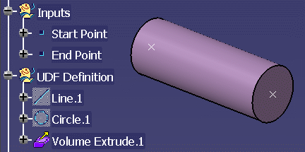
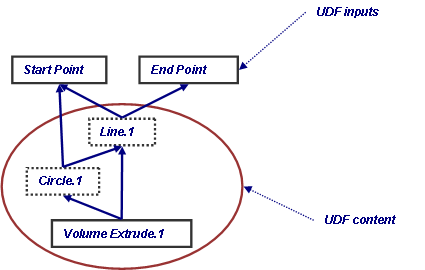
Inputs of a UDF are deduced from its content.
UDF Characteristics
UDFs for support geometry must have the following characteristics:
- The result of the UDF must be a surface.
- The inputs of the UDF (characteristic edges/faces of a profile) must follow a particular naming convention to be automatically retrieved when placing the small assembly.
- NOTE: If this naming convention is not used, you will have to manually select all the inputs (faces and edges) to place the small assembly.
- The geometry must be built using the Wireframe and Surface Design or Generative Shape Design workbenches. The Part Design workbench should not be used.
Guidelines for Creating Support Geometry
The orientation must be controlled.
- The faces provided in the templates are all oriented toward the
material to match the orientation of the plate and stiffener faces.
These templates are located in the following folder:
../OS/startup/EquipmentAndSystems/Structure/DetailingFeatures/UDFTemplates
- When using intersections between planes and/or surfaces, do not assume the orientation of the curves/lines because these orientations may change from one context to another. This is particularly true when using the Rotate feature because the orientation of the feature used as the Axis drives the orientation of the angle.
Do not assume surfaces are planar. Always design assuming a shell (twisted) stiffener and/or canted bulkhead. (If needed, generate planes tangent to the surface at a point near where you are creating geometry.)
Do not use a sub element as an input of another feature. Create explicit endpoints, or use one of the UDFs in the UtilityUDFs folder to orient the line or curve to provide consistent points that can be used to create additional geometry.
Use only Positioned Sketch so there is no doubt to which direction the U and V axis points.
Do not use offset constraints or distance dimensions because the orientation is not explicitly defined.
When using Sketcher, do not use 3-D objects directly. Intersect or project the geometry into the sketch plane. It is recommended you select these 3-D objects from the tree to avoid the possibility of selecting a sub element.
Try not to use input geometry
in knowledgeware rules or formulas [F(x)]. If you must to do so,
duplicate the geometry using the Offset
![]() command or the Join
command or the Join
![]() command, and reference the duplicated geometry in the rule or formula.
command, and reference the duplicated geometry in the rule or formula.
Using a Template to Get Started
To get started, use a template. To create the support geometry, the functional object(s) and the small assembly must be in the same CATPart.
Create contextual geometry (for example, a plate and a stiffener) in part bodies.
Use geometrical sets to organize the GSD data. The following sets are recommended:
- Inputs - Contain the extracted surfaces that are replaced when the UDF is instantiated
- UDF Definition - Contains all geometric elements to be included in the UDF.
Use geometrical sets within the UDF Definition to group similar activities and provide structure to the UDF.
Naming Conventions for Inputs
The following naming conventions must be followed so that the software can substitute the actual surfaces when the small assembly is placed.
- The first part of the name must be Plate or Shape followed by a number.
- The second part of the name must be Face or Edge.
- The third part of the name follows the convention shown below if the object is a stiffener. The third part will be either Standard or Reverse if the object is a plate.
- Edges will have a fourth part because the edge is defined by two faces.
- Each part of this name must be separated using an underscore. For example:
- Shape1_Face_MoldedFlange1
Shape2_Edge_Start_MoldedFlange2
Plate1_Standard
The following illustrates the naming conventions:

The current release introduces the keyword Support. This keyword allows the Small Assemblies command to enable multi-select for this particular input.
Naming Conventions for Typical I, L, T and U Shapes
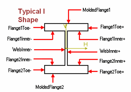
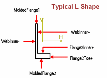
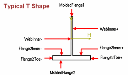
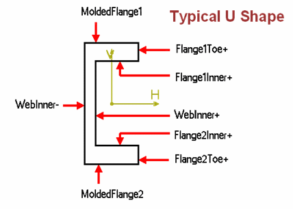
The parameters used to drive the geometry of the structural sections are also available for use in formulae when creating small assemblies.
The name of the parameter in the UDF has two parts. The first part identifies the plate or shape, while the second part is the name of the parameter in the parametric part used to create the section.
In the example below, Shape1_D is the height of the first shape selected. Shape2_Tw is the width of the web of the second shape selected.
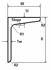
Typical parameters include:
D - Depth of the stiffener.
B - Flange width.
Tf - Flange thickness.
Tw - Web thickness.
R1 - Typically the radius between the FlangeInner face and the FlangeToe face.
R2 - Typically the radius between the WebInner face and the FlangeInner face.
Slope - Typically the angle on the inside of the flange.
- NOTE: These parameters do not get updated when the section of a stiffener is modified.
![]()