Creating a Part
|
|
This task shows how to create a part. | |
|
|
The process explained
here requires you to first build the graphic using Part Design. You do not
assign a type to the part first. The advantage of using this method is that
you can use the un-typed part again to create other types of parts. For
instance, you can use the same graphic for a coupling and a union. It is
recommended that you maintain separate directories for typed and un-typed
parts. You should also create a graphic representations file and specify where it is located. (See Defining Directory Paths and Define Graphic Representations for a Part.) Light parts do not have a graphic to begin with, so you have to use a modified process to create light parts. The initial steps are explained in Creating a Light Part. |
|
|
|
1. | Build a graphic using Part Design and save it. |
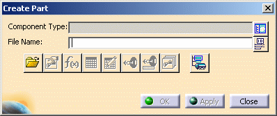
| 2. | Click the
Build Part button
|
|
| 3. | Click the Set Object Type
button |
|
| 4. | The File Open button is used to bring up a part, say, if you did not finish creating it and had to close the application. Clicking the File Open button opens a directory that is specified in the Project Resource Management file. You can also navigate to a different directory if you want to. You should only use this button to open a part that has already been typed. | |
| 5. | The Define Properties
button |
|
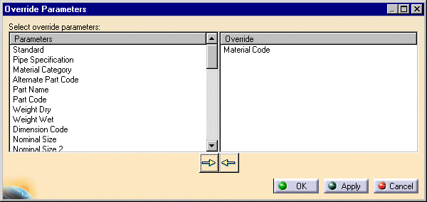
| 6. |
The Override
Parameters button For a stretchable part, such as a piping stretchable, the "Length" attribute must be defined as an override parameter.
|
|
| 7. | Click the Design Table
button |
|
| 8. | Click the Formula
button |
|
| 9. | The
Define Connector button
|
|
| 10. | The Connector Specs
button |
|
| 11. | The Manage Representations
button |
|
| 12. | Click the
Define ID Schema button
|
|
| 13. | You must save the part after you have made all your changes. Click Close or OK in the Create Part dialog box to exit he command. Select the part in the specifications tree, click File - Save as in the menubar and select a location for the part. | |
![]()