Deviation Annotations
A deviation annotation represents a measure at a specific location in a
certain direction. its value is expressed using a statistics law.
A deviation annotation is created either on an assembly component (leaf
assembly components type), on the assembly itself (parent
assembly components type) or on a support.
|
|
Refer to Creating Rigid Supports and Creating Flexible Supports. |
The deviation annotation of an assembly component or a
support is contained in its annotation set.
A deviation annotation is always associated with a
positioning system in order to specify how
the component is positioned when measured.
The deviation must not overlap with a degree of freedom used by its positioning system, therefore a point already used by a mechanical joint of the positioning system cannot be used by the deviation.
Input Annotations
Correspond to deviation annotations created on leaf assembly components or supports, they represent the input annotations or initial variation of the component before the assembly process.
The variation in the degrees of freedom restrained by the positioning system is null by definition.
|
|
The supports referenced by the mechanical joints of the positioning systems should be free of deviation (not referenced by a deviation). |
Output Annotations
Correspond to deviation annotations created on Parent assembly components, they represent the output annotations, annotations to be verified or measured during the assembly process.
|
|
Note: the output annotations' positioning system is not taken into account during computation, the positioning systems being taken into account are the ones associated to the activities. |
Positioning System
Reminder: a positioning system represents a set of mechanical joints for which you can lock or unlock translations or rotations.
The deviation positioning system must:
-
Be isostatic at least.
-
Be associated with the assembly component where the deviation is created.
-
Contain joints between support and the assembly component where the deviation is created.
-
Be empty when creating a deviation on a support.
|
|
|
Remarks
-
Component's deviation annotations always have the same positioning system.
-
Datum reference frame created with the 3D Functional Tolerancing & Annotations workbench may be used instead of a positioning system in a deviation.
-
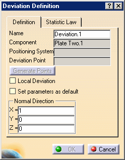
Clicking Generate Points button in the Deviation Definition dialog box generates default annotation points. These points are typical points where the component is the more flexible.

Note: Generate Points button remains grayed out until you select a positioning system
Creating Deviations (Step-by-Step Scenario)
-
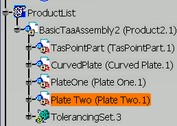
Select the Plate Two assembly component.

The Deviation Definition dialog box appears. 
In the Statistics Law tab you can select and define the desired law.
Six laws and their parameters are available:- Normal law:
- Mean
- Standard Deviation
- Uniform law:
- Minimum Limit
- Maximum Limit
- Constant law:
- Constant
- Pearson law:
- Nu
- Poisson:
- Lambda
- Snedecor:
- Degrees of freedom m
- Degrees of freedom n

Selecting the Local Deviation check box lets you take into account the deviation where it is defined or to interpolate it on the assembly component. - Normal law:
-
Keep the Normal law and the default parameters.
-
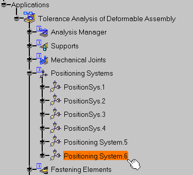
Select Positioning System.6.

-
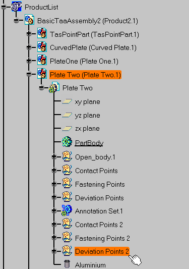
Select the Deviation Points 2 open body on Plate Two where the annotation will be created.


-
Click OK.

Six deviations are created: from Deviation1.1 to Deviation1.7.