It is not possible to re-use a point already used as a support (rigid or flexible).
This point can be:
- One, several or all the V5 Points from one or several V5 Open Body.
- One or several V4 mesh nodes from one or several V4 meshes.
A rigid support does not move during the assembly process.
The rigid support is stored in a CATPart document of the resource list.
-
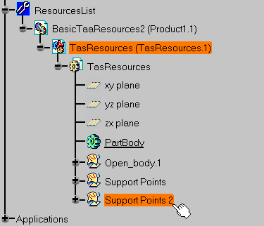
Select the component representing the tooling under the ResourcesList node of the PPR tree.

If the ResourcesList node of the PPR tree is empty, a resource product structure will be automatically created so that the user can select a resource component. The support created will be linked to the component selected. 
The Rigid Support Definition dialog box appears. 
-
Select the Support Points 2 open body.

All the points of the open body are selected. In this example three points. -
Click OK.

Three Rigid Support.20 items are created according to the selected points.