|
This task shows how to create a spine, that is
a curve normal to a list of ordered planes or planar curves. These spines
are useful when creating complex surfaces such as
swept, lofted,
or filleted surfaces. |
| |
|
|
Creating a Spine Based on Planes
|
|
|

|
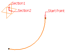
Open the Spine1.CATPart document. |

|
-
Click Spine
 from the Curves toolbar.
| The Spine Curve Definition dialog box is displayed. |
-
Successively select planes or planar profiles.
-
Click Preview.
| The spine is displayed. |
 |
-
You can also select a start point.
| The point is projected onto the first plane as the spine starting
point, as illustrated here (point.3 is selected) except if it is
already lying onto this first plane. |
-
Use the
contextual menu on the Start point field to create a point. (See
Stacking Commands).
-
If you do
not select a start point (default mode) one is computed
automatically.
-
To remove a
selected point, check the Computed start point option.
|
 |
-
Select one of the elements in the dialog box, then
click:
-
Replace, then select the replacing element in the geometry or
the specification tree
-
Remove
to delete it from the spine definition
-
Add
then select a new element to be added after the last one.
|
| Using the contextual menu, you can choose to Add After
or Add Before the selected element. |
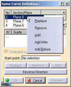 |
-
Click OK.
| The curve (identified as Spine.xxx) is added to the
specification tree. |
 |
When non planar curves are
selected, their mean planes are used to compute the spine. |
|
|
Creating a Spine Based on Guiding
Curves
|
|
|
Open the
Spine2.CATPart document. |
|
|
-
Click Spine
.
| The Spine Curve Definition dialog box is displayed. |
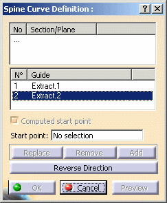 |
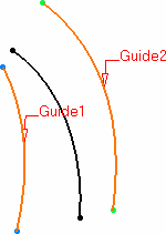
-
Click within the Guide list and successively select two
guiding curves.
| The spine is immediately previewed. |
 |
-
Click OK to create the spine.
| The curve (identified as Spine.xxx) is added to the
specification tree. |
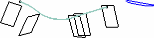
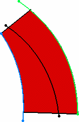
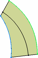
| This type of spine is very useful when creating a
swept surface, as illustrated below: |
 |
 |
| Swept surface without any spine |
Swept surface with specified spine |
|
| |
Reversing the Spine's Starting Direction
|
 |
This option can only be used if the first profile is a plane. |
|
|
Open the
Spine3.CATPart document. |
| |
|
|
|
-
Double-click the spine.
| The Spine Curve Definition dialog box is displayed. |
-
Click Reverse Direction.
-
Click OK to create the reverse spine.
|
|

|