This page covers the following topics:
Sketch Entities Aggregated by Sketch-based Features
The sketches used for creating sketch-based features are aggregated by, or to put it in another way, located just below those features in the tree when:
-
You are working in a hybrid design environment.
-
You are using a sketch created prior to the feature
-
The sketch is not already aggregated by another feature
Sketch Entities Referenced by Sketch-based Features
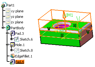
- Sketches are referenced by sketch-based features when these sketches
are already aggregated by previous features. In the example below, Pad.4
references Sketch.6 which is already use to create Pad.3.
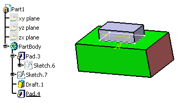
- Sketches are referenced by sketch-based features if these sketches
are not directly located above the node of the features you are creating.
In the example below, Pad 4 created using Sketch.7 because an
intermediary feature, Draft.1 was created after the sketch.
Specific Cases: Ribs, Slots, Multi-section Solids and Solid Combines
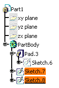
Ribs, slots, multi-section solids and solid combines require the use of two sketches at least.
- If these sketches are successively located in the specification tree,
like this... then, ribs, slots, multi-section solids or solid combines created from them aggregate them:

otherwise, each sketch is located according to the rules mentioned in the two previous paragraphs. For example, you will obtain this: 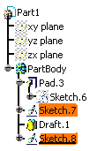
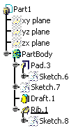
Specific Cases: Power Copies and User Features
When selecting a sketch-based feature to define a Power copy or a User Feature, remember that:
- if the sketch is aggregated (placed just below the feature in the specification tree), that sketch is included in the selection as shown under Inputs of components.
- otherwise, if the sketch is referenced, it is not therefore included in the definition of the power copy or user feature. If you need to include it because it will be requested at instantiation, do select it.
Reordering Sketch Locations
The rules mentioned above apply when you are creating sketch-based features. But when you are editing those features, at any time, you can modify the location of a sketch by using the Reorder capability. This capability moves and repositions sketches at the location of your choice, provided that the location you choose does not affect the integrity of your part. The application provides a quick help for that. For more information, refer to Reordering Features and Reordering Sketch-Based Features.