|
|
This task shows how to insert a Sequential Axial operation
in the program. To create the operation you must define:
Please refer to Sequential Axial and Sequential Groove Operations in the Reference section for detailed information about this operation. |
|
|
|
Open the Sequential_Axial.CATPart
document, then select Machining > Prismatic Machining
from the Start menu. Make the Manufacturing Program
current in the specification tree.
|
|
|
|
1. |
Select Sequential Axial A Sequential Axial entity along with a default tool is added to the program. The Sequential Axial dialog box appears directly at the
Geometry tab page
|
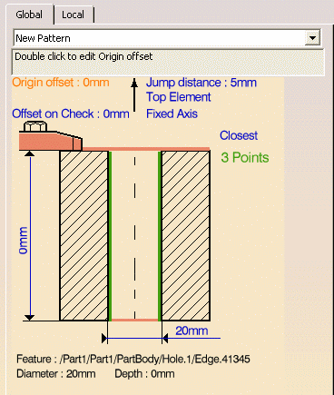
| The Global tab allows you to define the hole geometry to machine. | ||
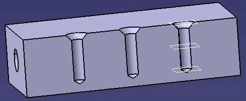
| 2. |
Select the red hole depth representation in the sensitive
icon, then select the three holes in the part. Just double
click to end your selections. The Global tab is updated as shown below.
|
|
| 3. |
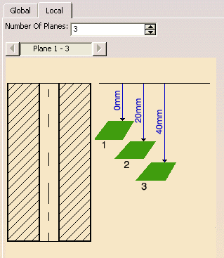
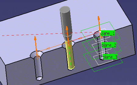
Select the Local tab to define the machining
planes to reach. Select the plane representations in the sensitive icon, and the desired planes in the part. The Local tab is updated as shown below.
|
|
| 4. |
Select the Strategy tab page
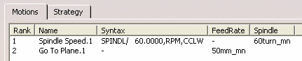
The Motions tab allows you to define the elementary motions making up the machining operation. |
|
| 5. |
Click Spindle Speed
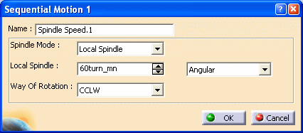 Click OK to add the first tool motion in the list in the Sequential Axial dialog box. |
|
| 6. |
Click Go to Plane
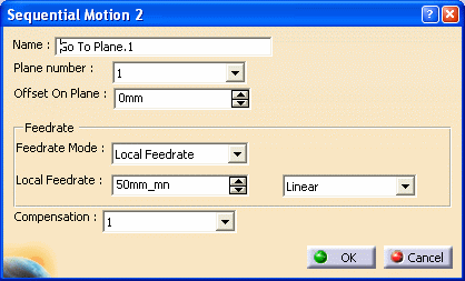 Click OK to add the second tool motion in the list. |
|
 |
||
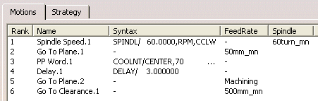
| 7. |
Insert other motions as follows:
|
|
 |
||
| 8. | Select the Strategy tab to specify machining parameters such as Approach clearance. | |
| 9. |
If needed, select the Tool tab page
See Edit the Tool of an Operation for more information about selecting tools. |
|
| 10. |
If needed, select the Feeds and Speeds
tab page
|
|
| 11. |
If you want to specify approach
and retract motion for the operation, select the
Macros tab page
The general procedure for this is described in Define Macros of an Operation. |
|
| 12. |
Check the validity of the operation by
replaying the tool path.
|
|
| 13. | Click OK to create the operation. | |
|
|
||