|
|
This task shows how to insert a
Facing operation in the program. To create
the operation you must define:
|
|
|
|
Open the
PrismaticMilling01.CATPart document, then select Machining >
Prismatic Machining from the Start menu. Make the Manufacturing
Program current in the specification tree. |
|
|
|
1. |
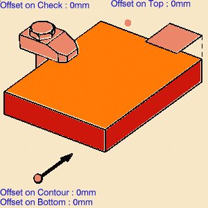
Select Facing
The Facing dialog box appears directly at the
Geometry tab page
|
|
|
The part bottom and flanks in the icon are
colored red indicating that this geometry is required for defining the
operation. All other geometry is optional. |
|
| 2. | Right click the red Bottom in the icon and
select Contour Detection from the contextual menu.
Click the red Bottom then select the underside of the part in the 3D window. The part boundary is automatically deduced thanks to the Contour Detection option. This is indicated by the highlighted Drive elements. |
|
|
|
The bottom and flanks of the icon are now colored green indicating that this geometry is now defined. | |
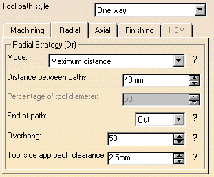
| 3. | Select the Strategy tab
page
You can then use the tab pages to set parameters for:
|
|
| 4. | Select the Tool tab page
|
|
| 5. | Select the Face Mill icon.
A 50mm diameter face mill is proposed. You can adjust the parameters as required. See Edit the Tool of an Operation for more information about selecting tools. |
|
| 6. | Select the Feeds and Speeds tab
page |
|
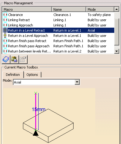
| 7. | Select the Macros tab
page
See Define Macros of an Operation for another example of specifying transition paths on a machining operation. |
|
|
|
Before accepting the operation, you should check its validity by
replaying the tool path.
|
|
| 8. | Click OK to create the operation. | |
|
|
In this scenario the operation used the
default start point (that is, the origin of the absolute axis system).
If you want to define a different start point, you can click the start point symbol in the sensitive icon then select a point. Please note that the exact position of operation's start point may be different from your selected point. The program will choose the nearest point from a number of possible start positions. |
|
|
|
||