-
Open file MoldWithMoldedPartAndComponents.CATPoduct in the samples/MoldAndPart directory.
-
Choose LeaderPin_FSN_1.1 in the specification tree or in the viewer
(this is an example, the labels will vary with the name of the component).
Use LeaderPin_FSN_1.1 object contextual menu.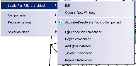
Open in New Window
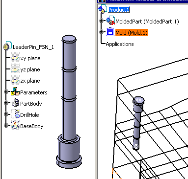
This opens the CATPart of the component in a new window, where you can edit it.
For example, we have changed the shaft angle of the LeaderPin in the new
window,
this change is taken into account in all the instances of the LeaderPin in
the Product.
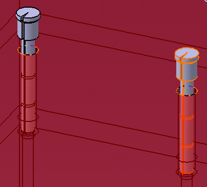
Activate/Deactivate LeaderPin Component
This is a toggle function, components that were already deactivated will
be activated and active components will be deactivated and displayed in visu
mode in the tree.

One component or a group of components may be selected for activation/deactivation.
Deactivated components are:
- not visible in the viewer nor are their associated holes,
- ignored when a bill of material is generated.
Edit LeaderPin Component
-
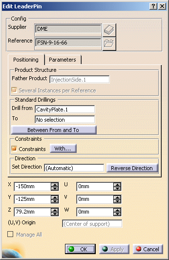
The component edition dialog box is displayed. Please refer to the Description of the Generic Dialog Box chapter for more information on the dialog box.
-
You can now modify the positioning of the component, its origin, its direction, the Drill from/To positioning and its parameters.
-
Click Reverse Direction or change the Origin X. You will see a preview of the result.
-
Pick the W green arrow on the graphic display to reverse the orientation or pick another point or face to change the position of the component. You will see a preview of the result.
-
You can also modify the component parameters in the Parameters tab. This tab is similar to that of the Define dialog box.
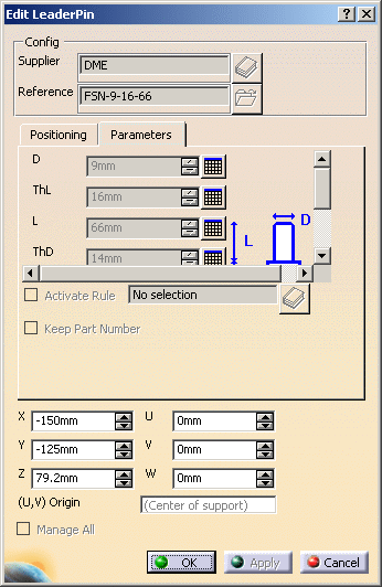
However in the Edit dialog box, you retrieve the complete list of the user parameters of the component, not only the standard ones:This is particularly useful to edit user components. -
Use the slider of the tab to browse all the data available.
-
Click OK to apply your modifications.