Click
![]() , then choose the desired Machining mode:
, then choose the desired Machining mode:
- Contact
- Between 2 curves with Tip or Side machining
- Between a curve and part with Tip or Side machining.
Select the geometry
![]() to be machined.
to be machined.
A number of strategy parameters
![]() are available for
defining:
are available for
defining:
- machining criteria
- radial conditions
- axial conditions
- finishing
- tool axis guidance
- cutter compensation (in Contact machining mode only).
Specify the tool to be
used
![]() ,
feeds and speeds
,
feeds and speeds
![]() , and
NC macros
, and
NC macros
![]() as needed.
as needed.
- The Stepover tab has been split into Radial and Axial tabs
- Tool path style has been moved from the Stepover tab to the Machining tab
- Sequencing has been moved from the Stepover tab to the Machining tab and enhanced
Multi-Axis Curve Machining: Strategy Parameters
Multi-Axis Curve Machining: Machining Parameters
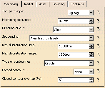
Tool path style
Indicates the cutting mode of the operation:
- Zig Zag: the machining direction is reversed from one path to the next
- One way: the same machining direction is used from one path to the next.
Machining tolerance
Specifies the maximum allowed distance between the theoretical and computed
tool path.
Direction of cut
Specifies how milling is to be done:
- Climb milling: the front of the advancing tool (in the machining direction) cuts into the material first
- Conventional milling: the rear of the advancing tool (in the machining direction) cuts into the material first
This parameter can be used to reverse the machining direction.

Specifies in which order the machining is to be done:
Radial first (by segment):
the order is axial machining first,
then the radial machining,
and all the levels of the current couple of relimitation points are machined
before the going to the next couple of relimitation points.
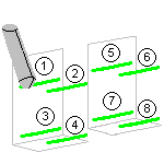
Axial first (by segment):
the order is radial machining first,
then the axial machining,
and all the levels of the current couple of relimitation points are machined
before the going to the next couple of relimitation points.
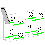
Radial first (by level):
the order is axial machining first,
then the radial machining,
and all the machining is done level by level.
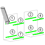
Axial first (by level):
the order is radial machining first,
then the axial machining,
and all the machining is done level by level.
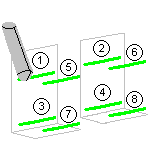
Ensures linearity between points that are far apart.
Maximum discretization angle
Specifies the maximum angular change of tool axis between tool
positions.
It is used to add more tool positions (points and axis) if value is
exceeded.
- The Maximum discretization step and Maximum discretization angle influence the number of points on the tool path.
- The values should be chosen carefully if you want to avoid having a high concentration of points along the tool trajectory.
- These parameters also apply to macro paths that are defined in
machining feedrate.
They do not apply to macro paths that do not have machining feedrate (RAPID, Approach, Retract, User, and so on). - Default value for Maximum discretization step is 100 m. Default value for Maximum discretization angle is 180 degrees.
Indicates whether the contouring type of corners is:
- Circular: the tool pivots around the corner point, following a contour whose radius is equal to the tool radius
- Angular: the tool does not remain in contact with the corner point, following a contour comprised of two line segments
- Optimized: the tool follows a contour derived from the corner that is continuous in tangent
- Forced circular: the tool follows a near-circular contour comprised of line segments.
Forced contour
Specifies whether the contour is to be forced open or closed.
Closed contour overlap
Specifies the percentage of overlap on the closed contour.
Multi-Axis Curve Machining: Radial Parameters
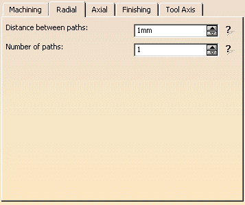
Distance between paths
Defines the maximum distance between two consecutive tool paths in a
radial strategy.
Number of paths
Defines the number of tool paths in a radial strategy.
Multi-Axis Curve Machining: Axial Parameters
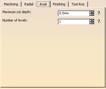
Maximum cut depth
This parameter is used in Contact or in Between 2 curves
modes when no auxiliary curve has been defined.
Defines the maximum depth of cut in an axial strategy.
Number of levels
Defines the number of levels to be machined in an axial strategy.
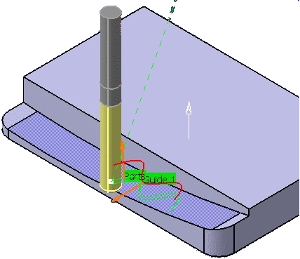
- In Contact mode, the tool follows the guide along the tool
axis direction until the part is reached,
according to the number of levels and the cut depth.
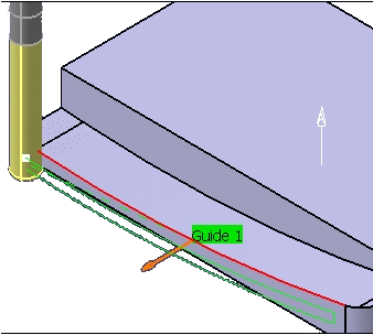
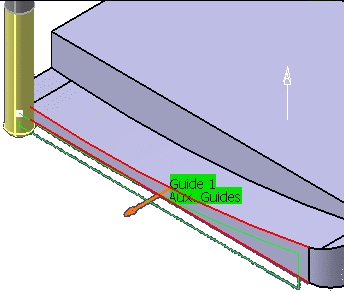
- In Between 2 curves mode, multi-level is done between the
guide contour and the auxiliary guide contour,
according to the number of levels.
Axial offsets on each contour are useful to restrict or extend the multi-level zone.
If no auxiliary curve is defined, the cut depth is used to simulate an auxiliary curve as an offset below the guide contour.
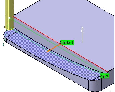
In Between curve and part mode, multi-level is
done between the guide contour and the part,
according to the number of levels.
Multi-Axis Curve Machining: Finishing Parameters
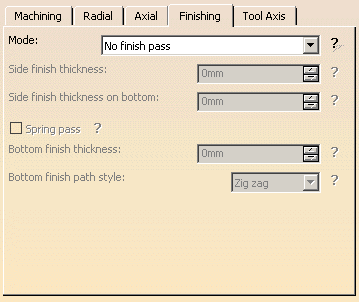
Finishing mode

Indicates whether or not finish passes are to be generated on the sides and
bottom of the area to machine.
Side finishing can be done at each level or only at the last level of the
operation.
Side finish thickness
Specifies the thickness used for side finishing.
Side finish thickness on bottom
Specifies the thickness used for the last side finish pass at the end of
the operation.
Bottom finish thickness
Specifies the thickness used for bottom finishing.
Bottom finish path style
Defines the bottom finish path style: Zig zag or One way.
Spring pass
Indicates
whether or not a spring pass is to be generated on the sides in the same
condition as the previous Side finish pass.
The spring pass is used to compensate the natural `spring' of the tool.
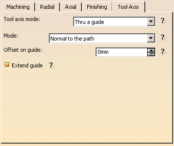
Multi-Axis Curve Machining: Tool Axis Parameters
Tool axis guidance
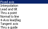
Specifies how the tool axis is to be guided.
For better performances and quality of the tool path, we recommend that
you choose a tool axis as close as possible to the normal of the surface to
be machined.
Below you will find the explanations of the various Guidance types and
tool axis modes,
then the explanations of the associated parameters.
(Only Tool Axis Parameters tabs containing parameters have been captured)
Lead and Tilt
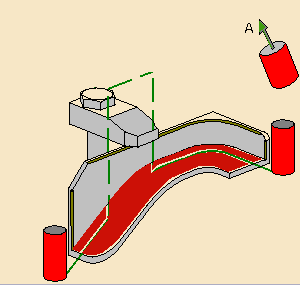
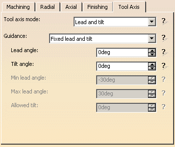
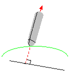
For Contact machining, the tool axis is normal to the part surface with
respect to a given lead angle
in the forward tool motion and with respect to a given tilt angle in the
perpendicular direction to this forward motion.
For Tip and Side machining, the tool axis is normal to the guides with
respect to a given lead angle in
the forward tool motion and with respect to a given tilt angle in the
perpendicular direction to this forward motion.
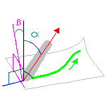
There are several types of lead and tilt modes as follows:
![]()
- Fixed lead and tilt:
Here both the lead and tilt angles are constant.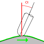
- Variable lead and fixed tilt:
Here the tool axis is allowed to move from the specified lead angle within a specified range,
the tilt angle remaining constant.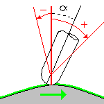
- Fixed lead and variable tilt:
Here the tool axis is allowed to move from the specified tilt angle within a specified range,
the lead angle remaining constant.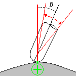
Fixed Axis
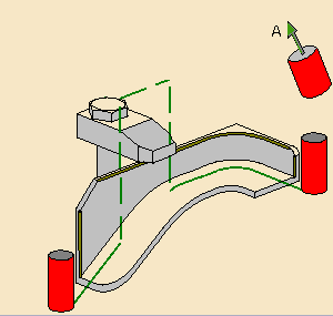
The tool axis remains constant for the operation.
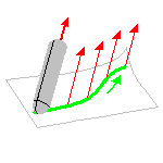
Interpolation
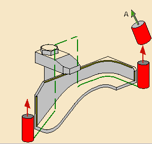
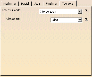
The tool axis is interpolated between two selected axes.
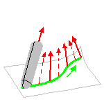
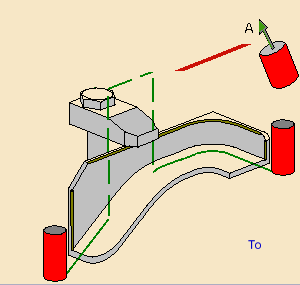
Thru a Point
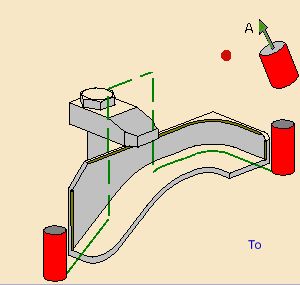
The tool axis passes through a specified point.
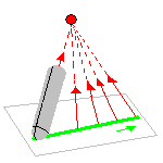
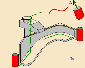
The tool axis can be oriented to point To
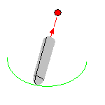
or From the point.
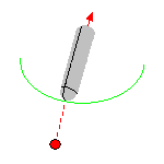
Normal to Line
The tool axis passes through a specified curve, and is normal to this
curve at all points.
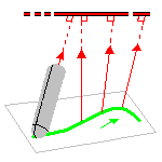
The tool axis can be oriented to point To
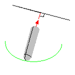
or From the line.
4-Axis Lead/Lag
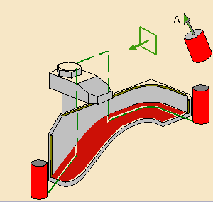
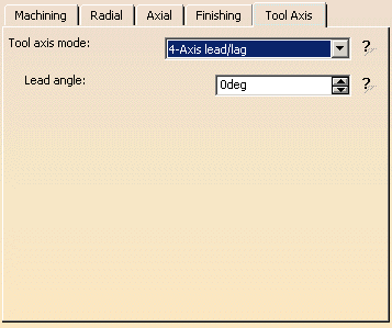
The tool axis is normal to the part surface with respect to a given lead
angle in the forward direction
and constrained to a specified plane.
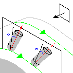
The tool axis is computed like in Lead and Tilt mode and then projected
into the constraint plane.
Optimized Lead

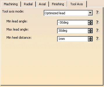
For Contact machining only.
The tool axis is allowed to vary from the specified lead angle within an
allowed range.
The allowed range is defined by Minimum and Maximum lead angles.
The back of the cutter is to be kept clear of the part by means of a Minimum
heel distance.
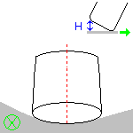
Optimized lead works as follows:
- lead defined as minimum to fit the part curvature
- lead increases if necessary to respect the Minimum heel distance.
If the required lead is outside the allowed range, the tool position will
not be kept in the tool path.
The maximum material removal is obtained when the tool curvature along
the trajectory matches the part curvature.
Tangent Axis
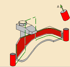
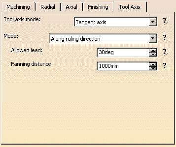
Tangent axis guidance is available for Between 2 Curves
and Between curve and part machining modes only.
Note that a cylindrical tool should be used.
The Tangent axis modes are as follows:
![]()
- Along ruling direction
Dedicated to milling walls made of a set (strip) of ruled and developable surfaces (possibly with some planar ones),
by mapping the tool axis to the ruling direction of the drive surfaces.
Maximum material removal is obtained when ruling direction on drive surface matches the ruling direction on tool.
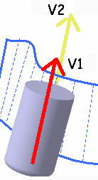
V2=drive surface ruling direction
V1=tool ruling direction - Along isoparametric lines
Recommended when the drive surfaces are ruled (even if not developable), ruling directions are the isoparametric lines
of the surfaces. The tool axis is mapped to the isoparametric lines (the one which is least parallel to the drive curve).
This is done even if the surface is planar, or it is not developable.
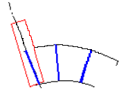
When machining a strip (or band) of drive surfaces, the best matching u or v isoparametric line of the first machined face
is deduced from the reference tool axis.
For the next machined face, the program analyzes the zone near the adjacent faces,
and chooses the isoparametric line that assures best continuity of the trajectory.
Machining continues in this way in the order of the faces in the strip.
If several drives surfaces are selected they must be in a continuous strip or band (that is, one after the other).
This behavior is available for operations created as from Release 12.
- Drive surface in cyan, Isoparametrics line in dash blue, two tangents planes in purple and the tool in yellow.
- Front view:
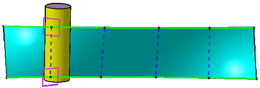
- Top view:
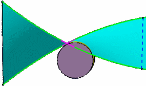
- Back view:
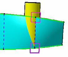
The two different planes generate the intersection between the tool and the drive surface.
When two consecutive drive surfaces do not have parallel isoparametric
lines, this creates an unwanted tool axis variation.
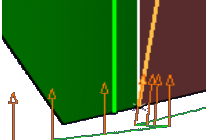
To avoid this, you can define a
Fanning distance that will be applied before and after the
seam of the two drive surfaces.
Within this fanning distance, the tool will remain tangent to the drive
contour and the tool axis will be interpolated :

In some cases, when fanning is applied to two areas that are very close
to each other,
those two areas are merged into a single area.

- Normal to drive curve
Recommended when the isoparametric lines of the drive surfaces are not compatible with the NC machine travel limits.
This may lead to collision with the machine head or loops in the tool path.
In these cases, the user wants the tool axis to be tangent to the drive surface, and normal to the drive curve.
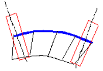
For Along isoparametric lines and Normal to drive curve Tangent Axis
guidance,
because the tool axis is not always the ruling direction of a developable
surface, some undercuts or overcuts may occur.
In this case, the maximum and minimum deviations to the drive surfaces are
displayed at the end of the computation.
Lead angle
Specifies a
user-defined incline of the tool axis in a plane defined by the direction of
motion and the normal to the part surface.
The lead angle is with respect to the part surface normal.
Maximum lead angle
Specifies a maximum lead angle.
Minimum lead angle
Specifies a minimum lead angle.
Allowed lead
Specifies
the range of allowed lead variation
(available when the tool axis is guided in Tangent Axis along a ruling
direction).
Tilt angle
Specifies a
user-defined incline of the tool axis in a plane normal to the direction of
motion.
The tilt angle is with respect to the part surface normal.
Allowed tilt
Specifies
the range of allowed tilt variation.
Minimum heel distance
Allows the back of the cutter to be kept clear of the part
(for example, when machining a smooth concave ruled part with Optimized Lead
tool axis guidance).
Fanning distance
Specifies a distance over which tool fanning takes place
(available when the tool axis is guided in Tangent Axis along a ruling
direction).
Default orientation of drive surfaces
In Lead and Tilt or 4-Axis Lead/Lag, the drive surface orientations are initialized in the following way:
- If the drive surface belongs to a solid, it is oriented away from the material.
- If the drive surface belongs to a wireframe element, it has the same orientation as the reference tool axis.
Multi-Axis Curve Machining: Cutter Compensation Parameters
(Double-click the part operation and push the Machine icon to open the Machine Editor)
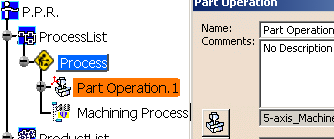
The following concerns the Curve Machining in Contact mode only.
In the Machine Editor, the Compensation tab contains options for:
- globally defining the 3D contact cutter compensation mode: None/Contact/Tip & Contact
- imposing the compensation mode to all operations supporting the
selected mode
whatever the choice defined at machining operation level.
If the options are set as follows, compensation can be managed at
machining operation level.

In this case a Compensation tab appears in the Strategy page
of the machining operation editor,
and the following options are available.
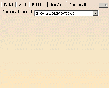
Output type
Allows you
to manage the generation of Cutter compensation (CUTCOM) instructions in the
NC data output:
The following options are proposed:
The tool contact point will be visualized during tool path replay.
Cutter compensation instructions are automatically generated in the NC data
output.
An approach macro must be defined to allow the compensation to be applied.
Example of generated APT source:
$$ Start generation of : Multi-Axis Curve Machining.1

      FEDRAT/ 1000.0000,MMPM

      SPINDL/ 70.0000,RPM,CLW

      CUTCOM/NORMPS

      $$ START CUTCOM NORMPS XC, YC, ZC, XN, YN, ZN, I, J, K

      .../...

      CUTCOM/OFF

      $$ END CUTCOM NORMPS XC, YC, ZC, XN, YN, ZN, I, J, K

      $$ End of generation of : Multi-Axis Curve Machining .1
Cutter compensation instructions are not automatically generated in the
NC data output.
However, CUTCOM instructions can be inserted manually.
For more information, please refer to How to generate CUTCOM syntaxes
provided in the Prismatic Machining User's Guide.
Multi-Axis Curve Machining: Geometry
A Multi-Axis Curve Machining operation can be created in one of the following Machining modes.
Contact
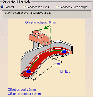
Tool follows the trajectory defined by the projection of the guiding
contour on the part surface
while respecting user-defined geometry limitations and machining strategy
parameters.
You can specify the following Geometry:
- Part surface with possible Offset on Part.
- Guiding contour (edges or sketch) with possible Offset on Contour.
- A Start point and End point with possible Offsets.
- Fixture or check elements with possible Offset on Check.
Between 2 curves
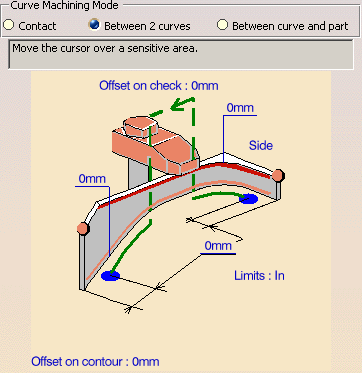
Tool follows a trajectory defined by the Guide contour and Auxiliary
Guide contour
while respecting user-defined geometry limitations and machining strategy
parameters.
You can specify the following Geometry:
- Guide contour and Auxiliary Guide contour (edges or sketch) with
possible global radial Offset on Contour and
an Axial Offset on each contour. - Start point and End point with possible Offsets
- Fixture or check elements with possible Offset on Check.
Guide contour is used for positioning the flank of the tool (radial positioning).
Auxiliary Guide contour is used for positioning the tool tip along the tool axis (axial positioning).
If no Auxiliary Guide contour is specified, the Guide contour is used for positioning both the flank and the tip of the tool.
Between a Curve and part
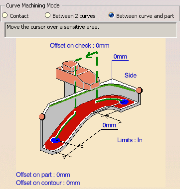
Tool follows trajectory defined by a top guide curve and bottom surfaces
while respecting user-defined
geometry limitations and machining strategy parameters.
You can specify the following Geometry:
- Part with possible Offset on Part.
- Guiding contour (edges or sketch) with possible Offset on Contour:
- A Start point and End point with possible Offsets.
- Fixture or check elements with possible Offset on Check.
- Axial height (when several axial levels are defined).
Those contours can be selected using the Edge Selection Toolbar.
A Guide.x element is displayed for each continuous ordered contour.
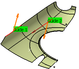
The side to mill is shown by the orange arrow. Click on the arrow to inverse this side to mill.
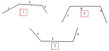
The linking macro is used to link two discontinuous tool path of the same
radial path.
Otherwise, a straight line is generated.
the following contextual menus become available:
On a guide
in the graphic area:
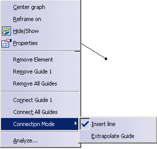
On a guide in the dialog box icon:
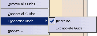
Removes the selected element from the Guide.
You can also remove an element by picking it again, after having launched
the Edge Selection Toolbar.
If the guide is no longer continuous, an other guide is created.
Before
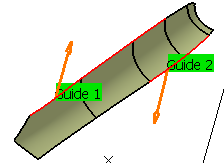
After
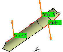
If the element picked is connected to that guide, it is automatically added to that guide.
If the element picked is connected to two guides, the element is added and the two guides are merged into one.
Removes the selected guide.
Before

After
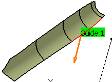
Removes all guides
Before
After
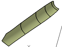
Connects a guide to another one.
Select the original guide, then the item Connect Guide.x in the
contextual menu and the target guide.
Before
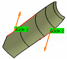
After
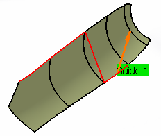
The connection is done either by inserting a line or extrapolating a
contour.

Connects all guides into one.
Before

After

Collision Checking is also available.
Multi-Axis Curve Machining: Tools
Recommended tools for Multi-Axis Curve Machining are End Mills, Face Mills, Conical Mills and T-Slotters.
Multi-Axis Curve Machining: Feeds and Speeds
In the Feeds and Speeds tab page, you can specify feedrates for approach,
retract, machining
and finishing as well as a machining spindle speed.
Feedrates and spindle speed can be defined in linear or angular units.
A Spindle output checkbox is available for managing output the SPINDL
instruction in the generated NC data file.
If the checkbox is selected, the instruction is generated. Otherwise, it is
not generated.
Feeds and speeds of the operation can be updated automatically according
to tooling data and the Rough or
Finish quality of the operation.
This is described in
Update
of Feeds and Speeds on Machining Operation.
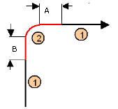
Feedrate Reduction in Corners
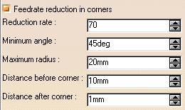
You can reduce feedrates in corners encountered along the tool path
depending on values given in the Feeds and Speeds tab page:
1=Machining feedrate or Finishing feedrate
2=Reduced feedrate
A=Distance after corner
B=Distance before corner
Feed reduction is applied to corners along the tool path whose radius is
less than the Maximum radius value
and whose arc angle is greater than the Minimum angle value. Corners can be
angled or rounded.
For Multi-Axis Curve Machining, feedrate reduction applies to inside
corners for machining or finishing passes.
It does not apply for macros or default linking and return motions.
If a cornering is defined with a radius of 5mm
and the Feedrate reduction in corners set to a lower radius value, t
he feedrate will not be reduced.
Multi-Axis Curve Machining: NC Macros
You can define transition paths in your machining operations by means of
NC Macros.
These transition paths are useful for providing approach, retract, return,
and linking motion in the tool path.
- An Approach macro is used to approach the operation start point.
- A Retract macro is used to retract from the operation end point.
-
A Linking macro may be used in several cases, for example:
- to link two non consecutive paths
- to access finish and spring passes.
- A Return in a Level macro is used in a multi-path operation to link
two consecutive paths in a given level.
It comprises an approach and a retract path. - A Return between Levels macro is used in a multi-level machining
operation to go to the next level.
It comprises an approach and a retract path. - A Return to Finish Pass macro is used in a machining operation to go
to the finish pass.
It comprises an approach and a retract path. - A Clearance macro can be used in a machining operation to avoid a fixture, for example.
