and Isoparametric Machining.
The Collision Checking parameters are accessed in the Geometry tab page of the operation's dialog box.
You will find below information on:
- Collisions with Part Elements for all Multi-Axis operations,
- Collisions with Check Elements for all Multi-Axis operations,
- Collisions with Drive Elements for Multi-Axis Curve Machining only,
- Checking for Collisions between Tool and Guide Elements during Macro Motions, for Multi-Axis Curve Machining only
Collision checking can be performed on check and
part elements with the tool assembly
(that is, the complete shape of the cutter plus its holder) or the cutting
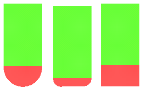
part of the tool (red part of following tools).
The cutting part of the tool is the lower component of the tool (see
picture below)
but not the part of the tool defined by the cutting length (Lc).
For a ball nose tool, the cutting part is the lower half sphere;
for a bull-nose tool, the lower half torus;
for a cylindrical tool, the lower cylinder.
To save computation time, use tool assembly
only if the geometry to be checked can interfere
with the upper part of the cutter.
Collisions with Part Elements
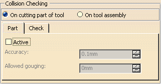
To activate collision checking on part elements, you must select the Active checkbox.
Part accuracy
Defines the maximum error to be accepted with respect to the part with
its offset.
This parameter is set to the machining tolerance value.
It can be only be changed by modifying the machining tolerance.
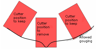
Allowed gouging
Defines the maximum cutter interference with the part during "linking
passes"
(including approach and retract motion).
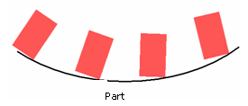
Collision checking with part elements is useful in the following cases:
- Concave part machined with Fixed tool axis mode.
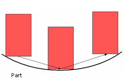
- Concave and non smooth part milled with 0 degree Lead angle.
Note that Allowed gouging must be set to a non zero value,
otherwise a "Nothing to Mill" message may be issued.
Collision checking on part elements is not useful in the following cases:
- Convex part machined with ball, flat or filleted ended tool or with
Fixed or Variable tool axis mode.
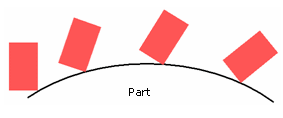
- Concave part milled with 0 degree Lead angle.
A "Nothing to Mill" message may be issued.
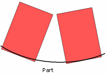
Minimum heel distance will keep the back of the cutter clear.
Collisions with Check Elements
For Multi-axis Sweeping, Contour Driven, Isoparametric Machining:
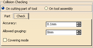
For Multi-axis Curve Machining:
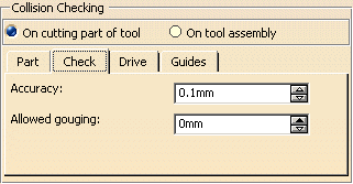
The parameters involved for check elements (such as fixtures) are described below:
Check (or Fixture) accuracy
Defines the maximum error to be accepted with respect to the fixture with
its offset.
Setting this parameter to a correct value avoids spending too much
computation time
to achieve unnecessary precision.
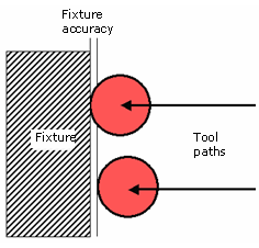
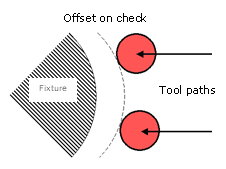
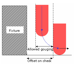
Offset on check
Defines theminimum distance between the cutter and the fixture, used to
limit the tool path.
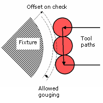
Allowed gouging
Defines the maximum cutter interference with the fixture during "linking
passes"
(including approach and retract motion).
The illustration below shows return motion with no macro or jump.
The illustration
below shows return
motion with macro between path and fixture.
Available for Multi-axis Sweeping, Contour Driven, Isoparametric Machining.
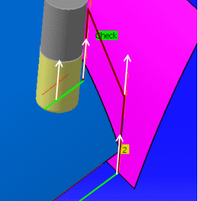
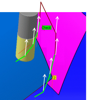
Select this option to optimize air cuts due to collision with the check.
In the example below, a Return in Level macro has been defined.
The Covering mode is not selected:
The Covering mode is selected, the air cut is reduced:
- You can apply a positive or negative offset on the check,
- The Covering mode applies to the tool path (in green), not to the macro motions (in red),
- The Covering mode applies to the whole set of check surfaces defined in the machining operation
Collisions with Drive Elements
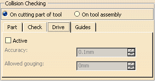
To activate collision checking onDrive elements, you must select the Active checkbox.
Drive Accuracy
Defines the maximum error to be accepted with respect to the drive with itsthickness.
Allowed gouging
Defines the maximum cutter interference with the driveduring "linking
passes"
(including approach and retract motion).
Checking for Collisions between Tool and
Guide Elements during Macro Motions
For Multi-Axis Curve Machining.
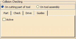
By default, the macro tool paths are not checked for collisions with
guiding elements.
If you select Active, all macro tool paths of the operation
will be checked for collision with guiding elements.