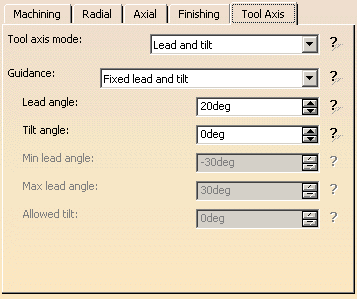
- the Curve Machining mode as Contact
- the geometry to be machined

- the tool that will be used

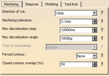
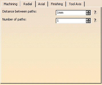
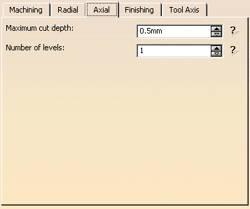
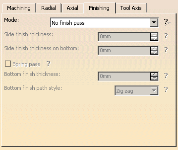
- the parameters of the machining strategy
 with the tool
axis guided in Lead and Tilt mode
Make the Manufacturing Program current in the specification tree.
-
Select the Multi-Axis Curve Machining icon
 .
.
The Multi-Axis Curve Machining dialog box appears directly at the Geometry tab page .
.
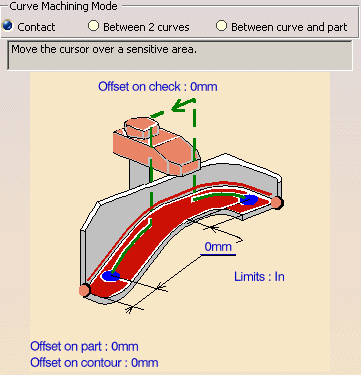
This page includes a sensitive icon to help you specify the geometry to be machined.
Set the Curve Machining mode to Contact to drive the contact point.
The part and guide curve in the icon are colored red indicating that this geometry is required for defining the operation.
All other geometry is optional.
-
Click the red part in the icon, then select the four faces in the 3D window as shown in the figure below.
-
Click the red guide element in the icon, then select four edges in the 3D window as shown in the figure below.
Note that a Guide is created for each set of continuous edges, and that discontinuous Guides are accepted.
The four faces and the four edges are selected:
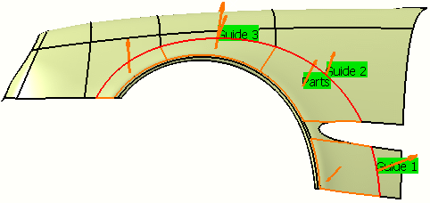
These are also indicated on the part. Make sure that the arrows representing the part surface orientation are all pointing upwards.
If the proposed tool is not suitable, just select the Tool tab page
This is described in Edit the Tool of an Operation.
-
Select the Feeds and Speeds tab page
 to
specify the
feedrates and spindle speeds for the operation.
select the Macros tab page
If a transition between two curves is smaller than the tool diameter, the clearance macro is not executed.
The tool continues straight on over the gap between the curves.
The general procedure for this is described in Define Macros of an Operation.
-
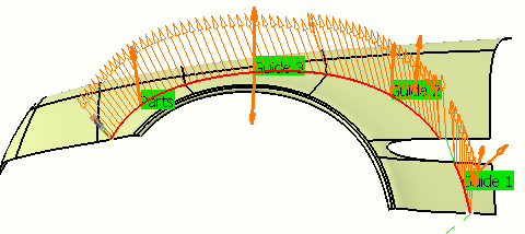
Check the validity of the operation by replaying the tool path.
-
Click OK to create the operation.
![]()
