 |
This task shows how to add tool changes in the program.
You can either:
The procedures below illustrates tool changes for axial
machining and milling operations. Differences for turning
operation tool changes are described in
Tool Changes for Turning Operations
below.
|
|
|
Insert a Tool Change Locally
|
 |
1. |
In the specification tree, select the program entity after
which you want to add the tool change. |
|
|
2. |
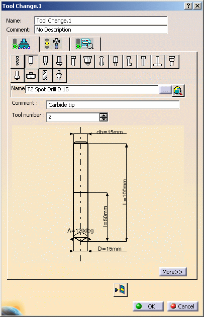
Select the desired icon in the Auxiliary Operations toolbar
(Tool Change
sub-toolbar). The corresponding dialog box appears
for defining the tool change.
|
|
|
|

|
|
|
3. |
Select the Tool tab
 in order to specify the tool to be referenced by the tool
change. You can do this by either:
- creating a new tool
- selecting another tool that is already used in the
document
- selecting another tool either in the document or
in tool catalogs by means of a query.
This is the same procedure as described in
Select or Create a Tool.
|
|
|
4. |
Select the Tool Assembly tab
 if you want to:
- create a new tool assembly.
In this case a tool assembly
is added to the Resource List.
Please refer to Edit a Tool
Assembly in the Resource List for more information
about how to specify the geometric and technological
characteristics of the a tool assembly.
- select a tool assembly that is already used in the
document.
|
|
|
5. |
Select the Syntax tab
 . .
- Select the Initialize from PP words table
check box to consult the tool change syntax defined
in the PP table that is referenced by the Part Operation.
- Otherwise, enter a PP instruction for
your tool change. This user-defined syntax has no link
with the PP table and its validity is not checked by
the program.
- If the PP Instruction comprises a sequence of PP
word syntaxes, you can choose the sequence to be used
by means of the Sequence number spinner.
|
|
|
6. |
Click OK to create the tool change in the program. |
 |
|
You can click Replay Tool Path
 to visualize the tool at the tool change point.
This point is specified in the current
Part Operation. |
|
|
Generate
Tool Changes Automatically
|
 |
1. |
Right-click the Manufacturing Program in the specification
tree and select
Generate Tool Changes. The program
is updated with all necessary tool changes. Each generated
tool change is inserted just before the first machining
operation in the program that requires the tool change.
|
|
|
|
Initial program:
MO1 using Tool1

						PP instruction

						MO2 using Tool2

						PP instruction

						MO3 using Tool2

MO4 using Tool3 |
Program after tool change generation:
Generated Tool change1

						MO1 using Tool1

						PP instruction

						Generated Tool change2

						MO2 using Tool2

						PP instruction

						MO3 using Tool2

						Generated Tool change3

MO4 using Tool 3 |
 |
|
To delete
tool changes that were automatically generated, right-click
the Manufacturing Program in the specification tree and
select
Delete Generated Tool Changes. All
tool changes that were automatically generated are removed
from the program.
|
|
|
 Tool Changes for Turning Operations
Lathe Tool Changes
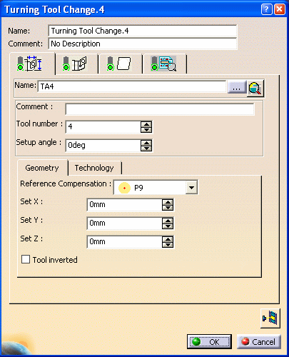
The Tool Change dialog box for Turning operations is
slightly different from the one shown above. The main
difference is that there are tab pages for the Tool Assembly, the Insert
Holder and the Insert.

However, the procedure for inserting tool changes is
the same.
Multi-Slide Lathe Machines
and Mounting Station
When a kinematic Multi-slide lathe machine (that is,
a CATProduct representation created using the NC Machine
Tool Builder product) is assigned to a Part operation, you
can specify a station for a tool/tool assembly on a tool
change activity by means of the Mounting station
combo.
When a new tool change is created, you can select where
this new tool/tool assembly is stationed on the turret by
selecting the empty stations on the turret from the Tool
Assembly tab (for a lathe tool assembly) or from the Tool
tab (for mill and drill tool/tool assembly) of the editor.
The selection or modification of a station is reflected
in the Turret Station Editor of the corresponding Manufacturing
Program.
|
|

|

