A new part operation is initialized in the manufacturing process and a Part Operation entity is added to the tree.
To access the parameters of the part operation, double-click the Part Operation entity in the tree or use the contextual menu. The Part Operation dialog box appears.
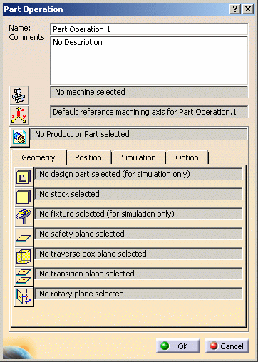
Name and Comment
Machine
Please refer to Machine Editor for more information.
Reference Machining Axis System
This is similar to the procedure described in Insert a Machining Axis Change.
Output coordinates will be expressed in the reference machining axis system. If a local machining axis system is inserted in the program, coordinates will be expressed in the local axis system.
Product or Part
Note: In a Manufacturing Hub context,
Product Instance Selection
![]() replaces Product or Part
replaces Product or Part
![]() in the Part Operation editor.
in the Part Operation editor.
Geometry tab
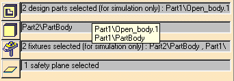
- Design part: Just click Design Part
 then select the desired geometry. This is useful if you want to do
material removal simulations later.
then select the desired geometry. This is useful if you want to do
material removal simulations later. - Stock: Just click Stock
 then select the desired geometry. This is useful for certain surface
machining operations and also for material removal simulations.
then select the desired geometry. This is useful for certain surface
machining operations and also for material removal simulations. - Fixtures: Just click Fixtures
 then select the desired geometry. This is useful if you want to do
material removal simulations later.
then select the desired geometry. This is useful if you want to do
material removal simulations later. - Safety plane: Just click Safety Plane
 then select the desired plane that will be used as a global safety plane
for the part operation.
then select the desired plane that will be used as a global safety plane
for the part operation. - Traverse box planes: Just click Traverse Box
Planes
 then select 5 planes that define a global traverse box for the part
operation.
then select 5 planes that define a global traverse box for the part
operation. - Transition planes: Just click Transition
Planes
 then select the desired planes that will be used as a global transition
planes for the part operation.
then select the desired planes that will be used as a global transition
planes for the part operation. - Rotary planes: Just click Rotary Planes
 then select the desired planes that will be used as a global rotary
planes for the part operation.
then select the desired planes that will be used as a global rotary
planes for the part operation.
- Traverse box planes and Transition planes to create linear tool path motions
- Rotary planes to create machine rotations:
- between machining operations
- between tool change and machining operation.
The Safety plane is not taken into account for the generation of transition paths.
Position tab
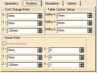
- Tool change point
For machines created using the NC Machine Tool Builder product, the tool change point is read from the machine and cannot be modified in the Part Operation.
For Multi-slide lathe machines, the tool change point is read from the machine and cannot be modified in the Part Operation.
- Table center setup
- Home point
You can select the check box to use the Home point defined on the machine.
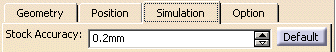
Simulation tab
Option tab
![]()
- Automatic stock selection for turning operations. This enables automatically updating the input stock for operations in a manufacturing program for turning (that is, turning operations and axial operations along the spindle axis). A lathe machine must be selected in this case.
![]()