You can also
select any face originated by Functional Features of any Functional Body. In
this case, the face needs to be the original untrimmed (unmerged) of the feature.
You
can also select any topological (trimmed) face of any Part Design body that is not the Part Body containing the active Functional Body.
-
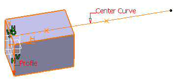
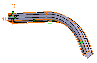
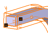
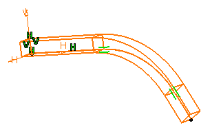
Select Sketch.2 as the profile you wish to
sweep.
If you launch the command with no profile previously
defined, just access the Sketcher by clicking the icon
 available in the dialog box and sketch the profile you need.
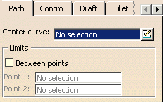
Path
|
 |
-
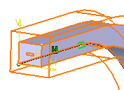
Click the Center curve field and select
Sketch.1 or click the Sketcher
icon to sketch the center curve you need.
Checking the Between points option defines the
sweep between two points along the path (other than the endpoints). You
merely need to select the points of your choice to define Point 1
and Point 2.
The Profile/Surface needs to be between the two
points along the path. When if the Profile/Surface is outside of the two
points, the feature will be created from the spot of the sketch on the
path keeping the same length of the distance between the two points.
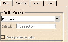
Control
|
 |
-
You can control the sweep position by choosing one of the
following options:
|
|
 |
|
|
| You can also
use any of the following creation contextual commands: |
|
|
For the purposes of our scenario, use the Keep angle option.
Checking the Cut end option cuts the sweep's end profile so
that it is normal to the end of the selected center curve.
The Move profile to
path option will sweep the sketch such that:
The Move profile to path capability
allows the user to obtain a simple associative between the profile and
the path, and also allows a single sketch to be swept along multiple
paths.
To access the Move profile to path
capability in Sweep, you need to follow the steps:
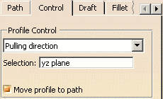
-
Sets the Profile Control to either Pulling
direction or Reference surface.
-
Turns on the Move profile to path
checkbox.
-
Builds the profile with the following
understanding:
-
The origin of the sketch plane (i.e. 0,0) will
be swept along the path.
-
The vertical axis of the sketch plane (i.e.
0,1) will be kept parallel to either the Pulling direction (if
profile control is set to Pull direction) or the normal to
the Reference surface (if profile control is set to Reference
surface).
-
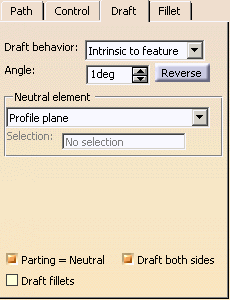
Click the Draft tab.
The Draft behavior field provides three options:
None: there is no draft. Intrinsic to feature: You can perform a draft
operation by defining the followings:
an angle value a neutral element
Profile plane: The default neutral element
defines a neutral curve on which the drafted face will lie. Plane/Surface:
If this is chosen, the Selection field is active.
You just need to select the plane or
surface of interest. In alternative to the selection of a plane/surface you can
select a sketch,
a sketch Output or a sketch Output Profile as profile, in this case a surface is automatically extruded along
the sketch plane normal.
Draft Properties: You can perform a draft
operation by defining the followings with the faces to be drafted.
Note: You need to define a
Draft
Properties
prior to a creation of the Prism to choose
Draft Properties in the pull down menu. See Faces to draft section.
-
a neutral element
-
Profile plane: The default neutral
element defines a neutral curve on which the drafted face will
lie.
-
Plane/Surface: If this is
chosen, the Selection field is active. You just need
to select the plane or surface of interest.
-
Use parting element: This option will be
available when Draft properties is selected. The
Neutral element is equivalent to the selected Draft Properties
Parting element.
-
Faces to draft: Faces to draft
functionality can control which faces are drafted.
There are three options:
-
All lateral faces: It is the default
neutral element (defines a neutral curve on which the drafted
face will lie).
-
Selected by pull direction: It will
automatically select the faces to draft to be those that are
parallel to the pull direction vector.
-
Select profile curves: This method allows
you to specify what faces to draft by picking curves of the
boundary profile. I.e.: the defining profile curve for the
face. You need to select Curves.
There are two options available:
|
Parting element
|
| When the Profile Plane or
Plane/Surface options are chosen to define the neutral element,
the Parting=Neutral option is active by default. Moreover,
when Parting=Neutral is active, the Draft both sides
option becomes active, too. If Draft both sides is on, the
draft will be symmetrical on the parting element.
Three options are available:
- Parting=Neutral
If this is chosen, the plane or surface you selected as the neutral
element is also used as the parting element.
- Draft both sides. If this is chosen, the draft
operation applies to both opposite directions from the parting
element.
- Draft fillets: If this is chosen, the fillets
are applied before the draft is created. Sometime small edges that
do not lie on the parting surface might be created. With this
option, the fillets will become the variable radius fillets instead
of the constant fillet and it prevents to generate the extra edges.
|
For the purpose of our scenario, set the Intrinsic to feature
option, the profile plane as the neutral element and then enter the value
of your choice to define the draft angle.
-
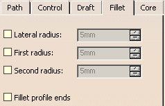
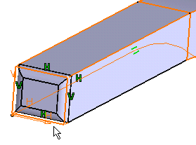
Click the Fillet tab.
-
Check the Lateral radius option if you wish to
fillet lateral edges. Then, you merely need to set the radius value of
your choice.
-
Check the First radius option if you wish to
fillet top edges. Then, you merely need to set the radius value of your
choice.
-
Check the Second radius option if you wish to
fillet the opposite bottom edges. Then, you merely need to set the radius
value of your choice.
-
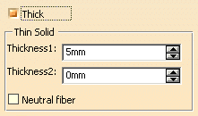
Check the Thick option. This option enables
you to add material to both sides of the profile.
Three additional options display:
-
To add thickness to the inside of the profile, for
example, enter 9mm in the Thickness1 field.
-
To add thickness to the outside of the profile, for
example enter 3mm in the Thickness2 field . The application
previews the new thickness.
-
To add material equally to both sides of the profile,
check Neutral fiber and click Preview to see the
result. The thickness you defined for Thickness1 is evenly
distributed.
Core (Specific to Shellable Features)
|
The Core capability enables you to define a core body
(offset) for a shellable feature.
 ,
then click the Sweep
,
then click the Sweep
 icon.
icon.