-
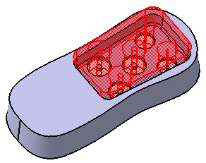
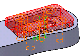
Note that the functional body contains a cutout. Cutouts are now displayed in red to improve the visualization of protected areas.
Click the Protected Feature icon
 .
.
Protected features can have different shapes. The Protected Feature dialog box that appears displays the Prism icon as the default shape to be created.
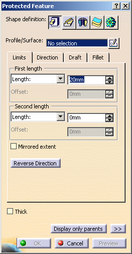
If you prefer a different shape, click any of the other four shapes available. To know how to create any of them, refer to the Prism, Sweep, Revolve, Thick Surface or External Shape tasks. For the purposes of our scenario, keep the default option.
-
Select Holes as the profile you wish to extrude. If no profile is defined, clicking the Sketcher
 icon enables you to sketch the profile you need.
 -
In the Limits tab, enter 20mm to define First length.
-
Optionally, set the parameters and options you wish to make the shape more complex as explained in Prism (or Sweep) page.
-
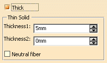
Check the Thick option that is available for the Prism, Sweep and Revolve shapes. This option enables you to add material to both sides of the profile.
Three additional options display:
-
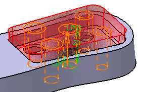
Enter 5mm in the Thickness1field and click Preview. Thickness is added to the inside of the profile. As a protected area, the protected feature is displayed in red.
-
Clear the Neutral fiber checkbox, enter 2mm in the Thickness2 field and click Preview. Thickness is added to the outside of the profile.
-
To add material equally to both sides of the profile, check Neutral fiber and click Preview to see the result. The thickness you defined for Thickness1 is evenly distributed: a thickness of 5mm has been added to each side of the profile.
-
Click OK to confirm and create the protected feature. Protected Prism.X is added to the specification tree in the Solid Functional Set.X node.
