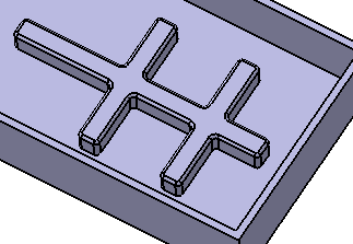
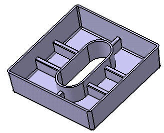
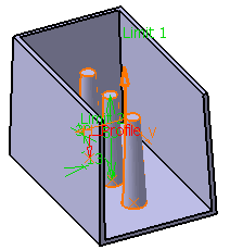
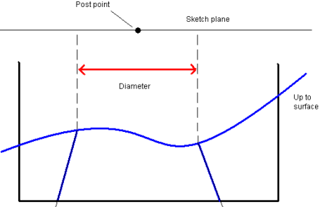
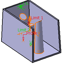
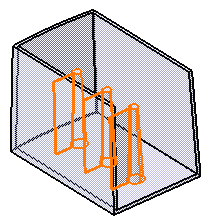
This task shows you how to create a rib.
-
Click the Rib icon
 .
.
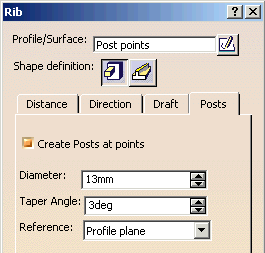
The Rib dialog box is displayed.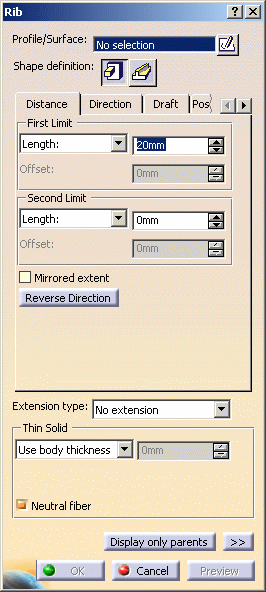
-
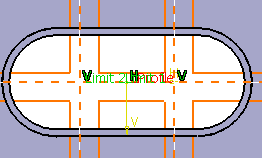
Select Sketch.3 as the closed profile. If no profile is defined, clicking the Sketcher
 icon enables you to sketch the profile you need.
 If you are not satisfied with the profile you selected, note that you can:
-
click the Profile/Surface field again and select another sketch.
-
use any of these creation contextual commands available from the Profile/Surface field:
-
Go to profile definition. See Using the Sub-elements of a sketch.
-
Create Sketch: launches the Sketcher after selecting any plane, and lets you sketch the profile you need as explained in the Sketcher User's Guide.
-
Create Join: joins surfaces or curves. See Joining Surfaces or Curves.
-
Create Extract: generates separate elements from non-connex sub-elements. See Extracting Geometry.
-
Shape Definition
The prism is the default shape. Just click the Sweep
 icon if you want to change. For the purposes of our scenario, keep the
default option.
 -
-
Set the parameters and options as follows to define the shape as explained in Prism (or Sweep) page.
-
In the Distance tab
First Limit: Length=20mm
Second Limit: Length=-50mm
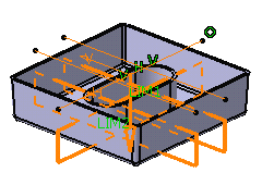
To define limits, instead of using the Length option, you can set the:
-
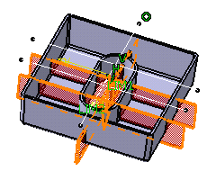
To shell option. This capability extends the rib to a shellable volume in the active body, in the opposite direction of the height. The extension of the rib profile must fit inside the boundaries of the shellable volume. Otherwise, no extension will occur.
Extension Type
-
-
To define the extension type you want, you can set one of the three options available from the Extension type drop down list:
-
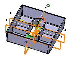
No extension: confines the rib to be created only within the walls of the shelled volume, even if the profile is outside of the walls of the volume.
-
Across removed face: Like no extension (above) except the rib is not confined within the wall of the deleted face of the shelled volume. Refer to Extend across removed faces option.

-
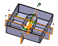
Add all: creates the rib based on the specified length and width values, even if the values cause the rib to protrude outside of the volume to which it is applied.
-
Subtract all: subtracts the volume of the rib from the volume to which it is applied.
-
-
For the purpose of our scenario, use the No extension option.
Thin Solid
To define the Thin Solid, you can set one of the two options available from the Type drop down list:
-
Use body thickness: the rib wall thickness is that of the active shelled body thickness.
-
Enter thickness: simply enter the value you want. After this option is selected, the value field becomes available. Wall thickness values can only by positive values.
-

