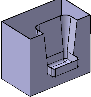
Pockets are based on simple profiles and usually have side walls and a bottom.
They also have an inner protected volume, which means that no other volumes in the same body can penetrate this area. If you add a pocket to a shelled body, it creates supporting walls, if necessary.
The direction of a pocket always goes from the inside to the outside of the body.
This task shows you how to create a pocket.
-
Click the Pocket icon
 .
.
The Pocket dialog box is displayed.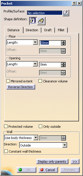
-
A pocket requires a closed planar profile. Select Sketch.2 as the profile defining the shape of the pocket. If no profile is defined, clicking the Sketcher
 icon enables you to sketch the profile you need.
If you are not satisfied with the profile you selected, note that you can:
-
click the Profile/Surface field again and select another sketch.
-
use any of these creation contextual commands available from the Profile/Surface field:
-
Go to profile definition. See Using the Sub-elements of a sketch.
-
Create Sketch: launches the Sketcher after selecting any plane, and lets you sketch the profile you need as explained in the Sketcher User's Guide.
-
Create Join: joins surfaces or curves. See Joining Surfaces or Curves.
-
Create Extract: generates separate elements from non-connex sub-elements. See Extracting Geometry.
-
Shape Definition
-
-
The prism is the default shape. Just click the sweep
 icon if you want to change. For the purposes of our scenario, keep the
default option.
 -
Set the parameters and options you want to define the shape as explained in Prism or Sweep page.
-
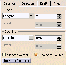
In the Distance tab
Floor: Length=20mm
Opening: Length=0mm
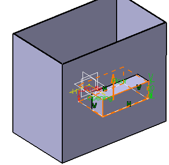
-
Select Reverse Direction button.
- Floor
- Opening
- Plane/Surface
-
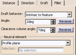
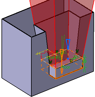
Click Draft tab. Select Intrinsic to feature in Draft behavior field. Enter 2deg for Angle and 7deg for Clearance volume angle.
-
Click Fillet tab. Check the Lateral radius and Floor radius option to fillet lateral edges and the floor edge with 5mm radius value.
-
To define the wall, you can set one of the two options available from the Type drop down list:
-
Use body thickness: the pocket wall thickness is that of the active shelled body thickness.
-
Enter thickness: simply enter the value you want. After this option is selected, the value field becomes available. Wall thickness values can only by positive values.
-
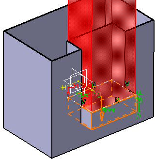
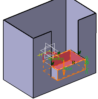
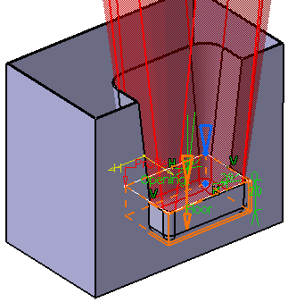
Checking the Clearance volume option in the Distance tab creates an infinite protected volume outside of the pocket and in the opposite direction in which the pocket depth is applied, which prevents any material from the same body from penetrating the area above the pocket. Here is a preview of the feature. As a protected area, the clearance volume is displayed in red:
 |
Checking the Protected volume option reserves space inside of the pocket. A protected volume is a space that nothing from the same body can penetrate inside of. As a protected area, the protected volume is displayed in red:
 |
Checking the Only outside option creates the pocket only outside of the shelled body. Thus, the profile of the pocket must extend outside of the walls in order for the pocket to be visible. This option is not available when Protected Volume is selected.
Draft |
If you wish to define a draft angle, just click the Draft tab and select Intrinsic to feature in Draft behavior field. And enter the desired value in the Angle field.
The default neutral element (defines a neutral curve on which the drafted face will lie) is the Profile plane. The other possible neutral elements can be:
 |
 |
Fillet |
The Lateral radius option enables you to fillet lateral edges.
The Floor radius option enables you to fillet bottom edges.
 |
 |
Wall |
