| 
     This task shows how to define the construction points which 
     will be used when routing the bundle segment to build the 
     Flexible Curve geometrical 
     representation. 
     They can be:
     
      | 
   
   
      | 
     The construction points or parts can also be located in another part of 
     the assembly. | 


       | 
     Make sure the following check box is selected to take advantage of the 
     associativity between the construction points or part and the bundle 
     segment.
     
       - 
       
Select Tools > Options.  
       - 
       
Select Infrastructure > Part Infrastructure, 
       then the General tab.  
       - 
       
Under External 
       References, select the Keep link with selected object 
       check box. 


      | 


     Defining Construction Points
      | 


       | 
     
     
       - 
       
Click Point
        . 


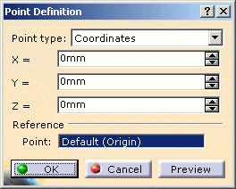
             | The Point Definition dialog box opens: | 


               | 


       - 
       
Select Coordinates as Point Type: 
       
        
       - 
       
Enter the respective coordinates for x, y, z.  
       - 
       
Click OK to validate. 
       The point is added to the specification tree in the container named as 
		Geometrical Set.  
      
      | 
   
   
     | 
     
      | 


       | 
     Open the 
     FollowOnPart1.CATProduct document. | 


       | 
     You cannot route branches on part surfaces using this 
     method. Refer to Routing Segments between Points 
     Created On-the-Fly. | 


       | 
     
     
       - 
       
Double-click the part to activate Electrical Harness 
       Installation.  
       - 
       
Click Point
        .  
       - 
       
Select On surface in the Point Type 
       list.  
       - 
       
Select the surface where the point is to be created.  
       - 
       
Optionally, select a reference point. 


             | 
           You can select an element to take its orientation as reference 
           direction or a plane to take its normal as reference direction. 
           You can also use the contextual menu to specify the X, Y, Z 
           components of the reference direction. | 


       - 
       
Enter a distance along the reference direction to display 
       a point.  
       - 
       
Click OK to create the point. 
       The point (identified as Point.x) is added to the specification tree.  
       - 
       
Repeat these steps for the other two points. 
       For more information refer to Creating 
       Points. 
       See also
       
       Creating Planes,
       
       Creating Lines.  
      
      | 
   
   
      | 
     
     
       At the end the document looks like this:  
       
      
      | 


       | 
     The construction constraints can be any structure elements (i.e. a 
     plane structure). |