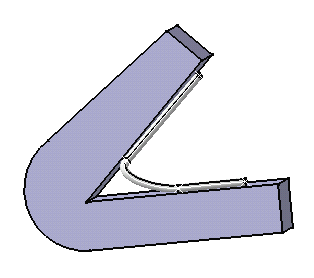
Note that it is possible to route branches/bundle segments on different surfaces preserving the bend radius definition.
- Since you are routing the branch/bundle segment on a surface, the associativity is not maintained.
- The Bundle segment on surface option is not available with
this function.
But you can change the side on which the bundle segment will be created on the surface using the Shift key. - It is possible to add or remove construction points or tangents instantly using the corresponding options. See Routing Options.
- This command also works in Visualization Mode so you do not need to load the context in design mode.
Select the Insert > Existing Component... item, and choose the FreeEdges1.CATPart document.
The path to this sample is: .../online/cfysm_C2/samples/FreeEdges1.CATPart.
-
Change the Product1 document into a geometrical bundle using Geometrical Bundle
 .
. -
Click Multi-Branchable Document
 .
.The Electrical Harness Assembly workbench switches to the Electrical Harness Installation workbench. The Branch Definition dialog box opens.
Enter the value of your choice for the different parameters. -
The Route Definition dialog box opens: 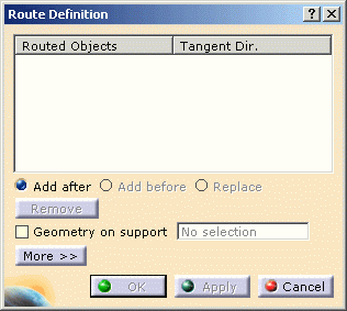
-
Press the Ctrl key and move the pointer along the geometry to display a manipulator and the tangent direction as shown:
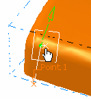

This manipulator follows the surface when you move its position.
It shows a point pre-positioned perpendicularly to the surface, with a distance to this surface equal to:- the radius in Automatic mode,
- the specified value in Manual mode,
- the radius increased with the safety margin value in Automatic with safety margin.
These modes are visible on clicking the More >> in the Route Definition dialog box.
-
Click successively where you want to define the flexible curve.
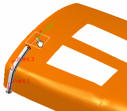
-
Releasing the Ctrl key ends the flexible curve definition.
-
You can modify the route by adding, replacing or removing points as well as modifying the tangent direction.
-
Click OK to validate.
The Route Definition dialog box closes.
The Branch/Bundle Segment Definition dialog box is displayed afresh. -
Click OK to validate the entries made.
The result looks like this: 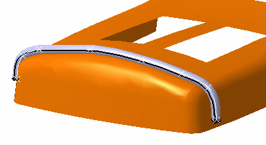
-
Optional - Click More >> to access to specific options:
Under the Offset Management at Creation frame:The default value is set to Automatic offset: The flexible curve follows the surface with an offset equal to the bend radius value. Automatic with safety margin: The radius of the flexible curve is increased with a safety margin value.
Manual: If you want to define the route at a selected point with a different offset.
For example:
-
You have started to draw the curve with the automatic offset, using the Ctrl key.
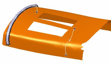
You want to change the route.
So release the Ctrl key and get access to the Route Definition dialog box. -
Select Manual and change the value if necessary.
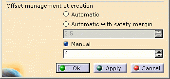
-
Press the Ctrl key again to follow the route definition.
Note: You can change the mode for only one point or more. -
Release the Ctrl key to end the route definition.
-
Click OK to validate the route definition.
-
-
Click OK to validate the branch/bundle segment definition.
The result looks like this: 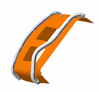
- In Automatic mode, the branch/bundle segment will keep in contact with the surface when the branch/bundle segment is modified.
- In Automatic with safety margin mode, if a protective covering exists, the offset equals the radius of the current bundle segment plus the thickness of the protective covering plus the safety margin entered by the user.
- The branch/bundle segment will not keep in contact with the surface if the surface is modified.
