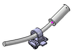
This task explains how to create/modify other segments at branch points.
Dedicated commands have been created to add
![]() and remove
and remove
![]() branch points although it is still possible to access them through the
Bundle Segment Definition dialog box.
branch points although it is still possible to access them through the
Bundle Segment Definition dialog box.
See also Modifying the bundle segment or protective covering geometry and formulas.
The tangent continuity is maintained between the segments.
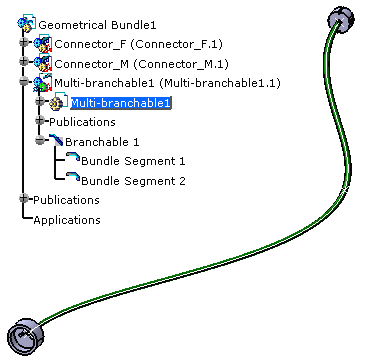
You can also connect other segments at branch points and manage the bundle segment diameter and color for each section.
The Branch Definition dialog box is still open.
-
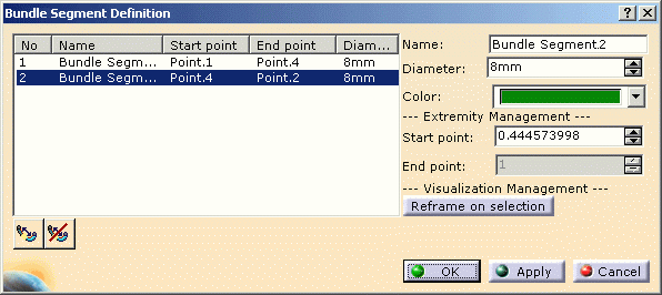
The Bundle Segment Definition dialog box opens: 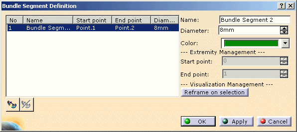
It lets you manage the bundle segments and their properties. -
Optionally, change the parameters according to your needs:
- Name
- Diameter
- Color.
-
Click Add Branch Point
 :
:
You are prompted to select the bundle segment. -
Select the bundle segment.
The Create Branch Point dialog box opens: 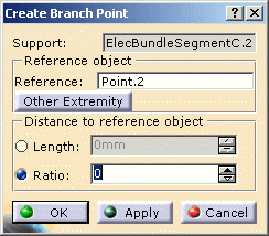
-
Click a point on the curve where you want to create a branch point.

The distance to the reference object is updated in the dialog box.
An alternative is to enter a value in the Length or Ratio field. -
Click OK to validate.
The branch point is not fixed as a bundle segment definition point but placed directly on the centerline. Thus, when modifying the centerline, the branch point follows the curve.
Modifying the bundle segment or protective covering geometry and formulas
Make sure you use Electrical Harness workbench when modifying the bundle segment or protective covering.
Using non electrical commands to modify electrical data may lead to inconsistencies when compared to the behavior implemented by electrical commands.
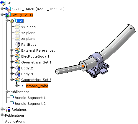
Directly editing, modifying and replacing either geometrical features created automatically (splits, curves, etc.) or formulas must be done with caution. Note that restructuring or reordering these features may also lead to unpredictable results.Let's see an example:
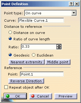
If you double-click the the selected branch point as shown above, you will activate the Point Definition command of the Generative Shape Design workbench.
This allows you to modify the point position, but out of the electrical context. In this case, the adaptative support will not be updated to the new bundle segment parameters.
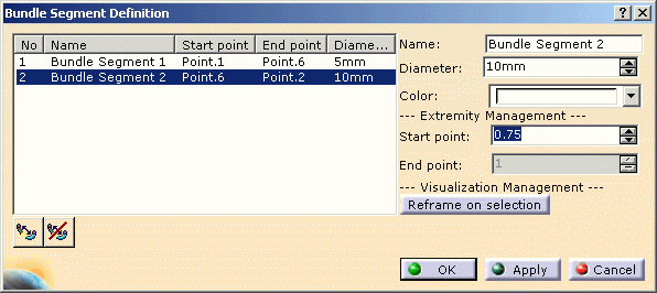
Using the dedicated command, the extremity management lets you modify the branch point position:
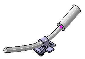
When you validate the entries made, the result looks like this:
