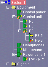
Connection Flags

This task shows how to rapidly identify where connections can still be made or where fine-tuning is required. This will help you, for example, to optimize the correspondence between the number of contact points and the number of connections to be made.

  1. Browse component connections in the tree view.

    Different types of connection flag are displayed on connected components in the tree view:
    • connectionflag03.gif (473 bytes)means that less than half the contact points under a given component have been connected.
    • connectionflag04.gif (111 bytes)means that more than half the contact points under a given component have been connected.
    • connectionflag02.gif (470 bytes)means that all contact points have been connected. No further connections can be made.
    • connectionflag01.gif (70 bytes) identifies where the fine-tuning is required.

    Note: Connections are considered properly made when the connection is established from the contact point.

    st11NLS.gif (11539 bytes)
  2. Make further connections as required (signal to component or component to signal) or fine-tune existing connections.

  3. To analyze all connections of the current system, click the Analyze Links View icon in the Workshop Commands toolbar.