Make sure you select the projection method you need (refer to About the angle projection methods below for more information). To do so:
-
Right-click Sheet.1 in the specification tree.
-
Select the Properties option from the displayed contextual menu.
The Properties dialog box appears with Projection Method options.
-
Select the First angle standard option.
-
In the Drawing window, click View Creation Wizard
 in the Views toolbar (Wizard sub-toolbar).
The View Wizard (Step 1/2) : Predefined Configurations dialog box is displayed.
-
Select the desired view configuration.
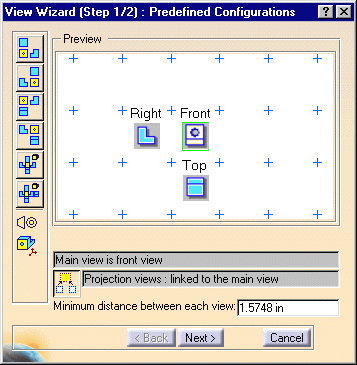
In our scenario, the ISO standard and the first angle projection method are used, and the following configurations are available:
-
 front, bottom and left
 -
 front, bottom and right
 -
 front, top and left
 -
 front, top and right
 -
 projection and isometric
 -
 projection, rear and isometric

With the ANSI standard and the third angle projection method, the configuration symbol  and the
configuration options displayed in the dialog box will be different.
To have the projection views linked to the main
view, click the
 option.
You can define the Minimum distance between each view. For this, enter the desired value in the modifiable field available in the View Wizard dialog box.
A preview is available. In this preview:
-
The main view corresponds to the view to which any other view will be linked, it can be either a front or an isometric view, and it has a green frame. This view will become the active view when you generate the desired views.
Any other view (front and/or isometric view) that can possibly become the main view has a black frame.
To turn a view into the main view, right-click it and select Set as main view. -
At any time, you can delete a view you inserted. To do so, right-click the view and select Delete.
-
Once you generate the views, if you move the main view, all the child views will move accordingly. You can right-click a view and select View Positioning > Position Independently of Reference View, if you need to move a child view independently from its reference view.
-
-
Click the Next > button in the View Wizard (Step 1/2) : Predefined Configurations dialog box.
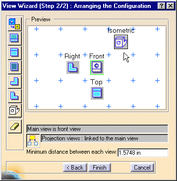
The View Wizard (Step 2/2) : Arranging the Configuration dialog box is now displayed with a new set of view buttons:
-
 front view
 -
 rear view
 -
 top
view
 -
 bottom view
 -
 left view
 -
 right view
 -
 isometric view
 -
 clear preview
-
-
Click the Isometric View button
 .
.
-
Position the isometric view onto the Preview window by dragging and clicking it as desired.
-
Click the Finish button in the View Wizard (Step 2/2) : Arranging the Configuration dialog box.
-
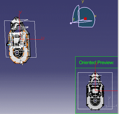
Select the CATPart document in the 3D window.
-
Click on the desired 3D part plane to be used as reference plane.
If the plane can be computed, the oriented preview of the 3D part appears as you move the cursor over the 3D part (planes).
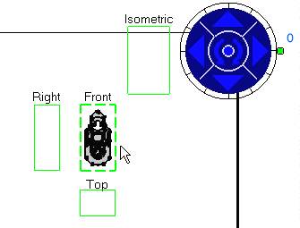
The views now appear on the CATDrawing document: they are previewed in green frames and can be reoriented thanks to the blue arrows that appear.
-
Go over the view frames with your cursor to visualize them.
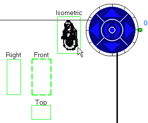
-
Use the blue arrows to reorient the views as desired. Then, go over the views with the cursor to check their preview. For more details, refer to Before You Begin > Defining the view orientation.
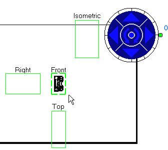
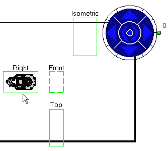

You can also modify the increment value using the contextual menu which is available for the green knob. To do this, right-click the knob and select the desired option from the contextual menu. For more details, refer to Before You Begin > Defining the view orientation. -
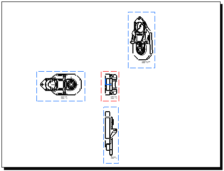
Once you are satisfied with the result, click on the sheet to create the views.
The front view is actually the main view and the isometric view is added to the predefined configuration.
About the angle projection methods
- The first angle standard method is an orthographic representation
comprising the arrangement, around the principal view of an object, of
some of all of the other five views of that object. With reference to the
principal view, the other views are arranged as follows:
- the view from above is placed underneath
- the view from below is placed above
- the view from the left is placed on the right
- the view from the rear is placed on the left or on the right, as
convenient.
(Ref. No. ISO 10209-2:1993)
- The third angle standard method is an orthographic representation
comprising the arrangement, around the principal view of an object, of
some of all of the other five views of that object. With reference to the
principal view, the other views are arranged as follows:
- the view from above is placed above
- the view from below is placed underneath
- the view from the left is placed on the left
- the view from the rear is placed on the left or on the right, as
convenient.
(Ref. No. ISO 10209-2:1993)
- The ISO and ANSI standards are independent from the angle projection method.
![]()