- What is the active view?
- Defining the view orientation during view creation
- Generated geometry
- Constraints
- 2D/3D associativity
- 2D/3D associativity on views
- 2D/3D associativity and view positioning
- 2D/3D associativity and update
- 2D/3D associativity after updating
- 2D/3D associativity on generated dimensions
- 2D/3D associativity and color
- 2D/3D associativity and operations performed on parts
- 2D/3D associativity and part infrastructure settings
- 2D/3D associativity for Approximate/CGR/Raster views
- 3D elements generated in views
- Dress-up generated in views
- Callout representation
- Warm Start and views
- View generation modes
What is the active view? |
|
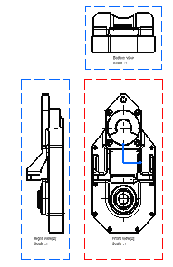 |
View frames can be of three different colors, depending on the view
status:
In the Drafting specification tree, specific icons are used to represent the view type (Front view, Projection view, Isometric view, etc). Refer to CATDrawing Specification Tree Icons for more information. To activate a view, you can either:
Axes are taken into account on active views. As a result, the frame of an active view will adapt to the elements included in this view. |
Defining the view orientation during view creation |
|
-
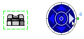
Click the right or left arrow to visualize the right or left side, respectively.
-
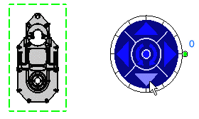
Click the bottom arrow to visualize the bottom side.
-
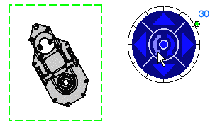
Click the counterclockwise arrow to rotate the reference plane.
-
Drag the green knob to redefine the rotating angle. The default increment value is 30 degrees.
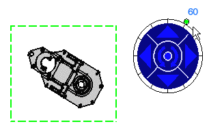
-
You can modify the increment value using the contextual menu which is available for the green knob. To do this, right-click the knob and select the desired option:
-
Free hand rotation: Lets you rotate the knob in a free manner using the mouse, instead of snapping it to a given increment.
-
Incremental hand rotation: Snaps the rotation to a given increment (from 30 to 30 degrees, between zero and 330). This is the default value.
-
Set increment...: Displays the Increment Setting dialog box. Enter the required value in the Increment value field. For example, type 5 deg (for 5 degrees) and click OK.
-
Set current angle to:
-
0 deg: Sets the current angle value to 0 degrees.
-
90 deg: Sets the current angle value to 90 degrees.
-
180 deg: Sets the current angle value to 180 degrees.
-
270 deg: Sets the current angle value to 270 degrees.
-
Set angle value...: Displays the Angle Setting dialog box. Enter the required value in the current angle (deg) field. For example, type 30 and click OK.
-
-
Generated geometry |
|
Dress-up settings of generated geometry
You can generate a number of geometry or dress-up elements, depending on the options you select in Tools > Options > Mechanical Design > Drafting > View tab.
For example, if you want the colors of a part to be automatically generated onto the views, check the Inherit 3D colors option.
Dress-up properties of generated geometry
You can change the properties of some geometry and dress-up elements after the view has been generated, provided you check the desired options in the Properties dialog box. To display it, choose Properties from the contextual menu and select the View tab.
In the following example, the graphical properties of two generated elements are overloaded. After an update of the part is performed, four items inherit the graphical properties of the 3D origin.
 3D part |
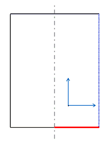 Modified generated item |
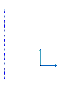 Generated item with the same 3D origin |
 3D part |
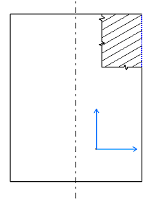 Modified generated item
|
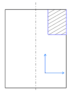 Generated item with the same 3D origin
|
|
|
|
|
|
Overloaded graphical properties are not kept for the following
generated items:
|
Definition of dress-up properties for generated geometry
The following table illustrates how the various dress-up properties of generated geometry are defined, depending on the view type.
|
View type |
||
|
|
|
|
|
Parameters |
||
|
Properties defined via Tools > Options > Mechanical Design > Drafting > View |
Properties generated in the view |
|
Properties defined via Tools > Options > Mechanical Design > Drafting > View |
Properties defined via Tools > Options > Mechanical Design > Drafting > View |
Constraints |
|
2D/3D associativity |
|
- 2D/3D associativity on views
- 2D/3D associativity and view positioning
- 2D/3D associativity and update
- 2D/3D associativity after updating
- 2D/3D associativity on generated dimensions
- 2D/3D associativity and color
- 2D/3D associativity and operations performed on parts
- 2D/3D associativity and part infrastructure settings
2D/3D associativity on views
A generative view results from specifications in a 3D document. This specification corresponds either to the whole document or to a feature in the document. This feature can be:
- a .model document
- a part document (the whole document or still one or more bodies)
- a product document (the whole document or still one or more assemblies)
2D/3D associativity and view positioning
Generative views are positioned according to the center of gravity of the 3D part. If you modify a 3D part in such a way that the center of gravity of the part changes, then, when updating the view, the position of the view will be re-computed according to the new center of gravity of the part and will be modified accordingly.
For more information on View Positioning properties, refer to the Generative Views Positioning Mode section in the Interactive Drafting User's Guide.
2D/3D associativity and update
Any modification applied to the specifications, before the generated views is/are updated, is detected. You can perform an update. You can update all views or a selection of views:
- The Update icon
 is active in the Update toolbar when a sheet (or drawing) contains views
that need to be updated (this can be all views in the sheet or some of
them only). You can update all views in the active sheet by clicking this
icon.
 - An Update symbol
 appears in the specification tree for the views that need to be updated.
You can update a selection of views by selecting and right-clicking the
views you want to update and choosing Update Selection
 from the
contextual menu. Only the items you select are updated. Update symbols
remain in the specification tree for the items that have not been
updated, so you always know which items are up-to-date and which are not.
 - Update symbols also appear in the specification tree to indicate
drawings
 and sheets
 containing views that
need to be updated. You can update all views in a given sheet (or in a
selection of sheets), by selecting and right-clicking the sheets and
then choosing Update Selection. You can also use the same
method for a drawing: this will update all sheets (and therefore all
views) in the drawing.
 - During an update process, a dialog box is displayed to show the
progress of the update.
When the update involves several views, a Cancel button is available in this dialog box. This allows you to interrupt the update. The view that is being processed at the time you click this button will be updated (i.e. the update of the current view will finish), and then the update will stop. The subsequent views will not be updated.
2D/3D associativity after updating
Use the following commands to update views:
- Click Update
 to update all views in the active sheet.
 - Select and right-click the views you want to update and choose
Update Selection
 from the
contextual menu to update a selection of views.
 - Type C:Force Update
 in the Power Input field to update the drawing in accordance with the 3D.
Be careful when doing this, as you may lose manual modifications applied
to the drawing.
During view update, the following operations are performed:
- associative section/auxiliary view profiles are re-computed
- the geometry is re-generated
- any annotation/dimension/dress up element linked to the generated geometry is re-computed
- in the case of elements (one or more) that have been graphically modified or deleted, these modifications/deletions are preserved, on the condition the view was up-to-date when you deleted or modified it.
- Note that you can restore deleted elements at any time by selecting the Restore Deleted option from the contextual menu and then updating the view. You can either use the Update icon if you modified the 3D part, or key in C:Force Update if you did not modify the 3D part.
- If you delete a generated item and subsequently perform an update, all items that have the same 3D origin as the deleted item will not be generated. Likewise, if you transfer a generated item to No Show and subsequently perform an update, all items that have the same 3D origin as the item in No Show will be transferred to No Show.
2D/3D associativity on generated dimensions
Generated dimensions are associative with the 3D part constraints on the condition you checked the Generation dimensions when updating the sheet option from the Options dialog box (Tools > Options > Mechanical Design > Drafting > Generation tab).
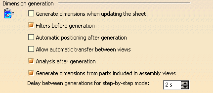
Note that these dimensions will be re-generated in accordance with the other options checked/un-checked in the Options dialog box.
2D/3D associativity and color
When you refresh a generated view you have modified, the colors are re-generated with the geometrical information from the part, and you might obtain unexpected results.
As an example, if you create this part...
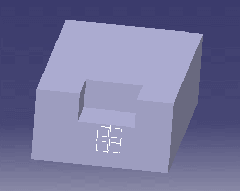
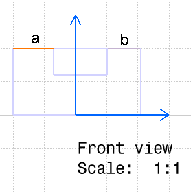
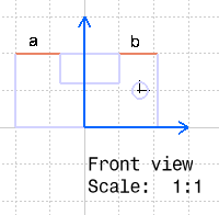
Note that modifications performed on the graphical properties (color, line type, line thickness) of a generated geometrical element (as is the case in our example above) are associative, i.e. such modifications are kept when updating the view later on. Also note that once you have overloaded the original properties of an element, you cannot reset it to its original properties.
2D/3D associativity and operations performed on parts
Operations performed on parts, and that can be saved with the part itself (such as Show/No Show, Delete, Deactivate, Visualization Filters, etc.), are taken into account when generating the view. For example, if you delete a part body, this body will not be represented on the generated view. If you then restore this part body, you can update the corresponding views; this time, the body will be represented on the generated view.
There is an exception to this rule: when generating views in exact mode, Define in Work Object is not taken into account. However, since this command is taken into account when generating views in CGR, Approximate and Raster modes, it is recommended to be wary of using Define in Work Object for such view types.
2D/3D associativity and part infrastructure settings
Settings used for a given part, and that only have an impact on the current session but cannot be saved with the part itself (such as the Display in Geometry Area category of settings available via Tools > Options > Infrastructure > Part Infrastructure > Display), have no impact on how or whether the part will be represented on the generated view.
2D/3D associativity for approximate/CGR/raster views
The up-to-date mechanism of Approximate, CGR or Raster
views from CATProduct documents (in current file environment), is based
on the document's inner date.
This mechanism is faster and less memory consuming than the current
Exact view mode up-to-date mechanism.
Due to this mechanism, if a CATPart or cgr or .model file is moved using
Save management... or Save As... , then this will
modify the last modification date, thus the views will be
not-up-to-date.
For more information, refer to Advantages and restrictions common to CGR and Approximate.
3D Elements Generated in Views
3D elements are handled differently depending on the view mode you are generating:
Exact mode
- All CATPart elements are supported.
- Exact Solid, Faces and Skin elements from .model documents are supported, as well as space ditto (with similar content of associated detail).
CGR and raster mode
- All CATPart elements except wireframe and 3D points are supported.
- All elements from .model documents are supported.
- External MultiCAD components are supported.
Dress-up generated in views
You can automatically create center lines, axis lines and threads according to the criteria described below. (Note that this criteria also apply to isometric views.)
Center lines
- The view plane must be perpendicular to the rotation face axis.
- The representation of the rotation face in the view must exceed 180 degrees.
 |
Axis lines
- The view plane must be parallel to the rotation face axis.
- Rotation faces made out of fillets are not taken into account when generating axis lines.
 |
Threads (represented from the front and rear)
- The view plane must be perpendicular to the rotation face axis.
- The face should be a threaded hole or a thread.
- The representation of the rotation face in the view must exceed 180 degrees.
 |
|
|
Threads will be represented from the front AND from the rear, whether or not the hole is threaded along its whole depth. |
Threads (represented from the side)
- The view plane must be parallel to the rotation face axis.
- The face should be a threaded hole or a thread.
 |
Callout Representation
You can specify that the size of callout elements should not be dependent on the view scale. You have two ways of doing this:
- After callout creation, right-click on the callout, select Properties in the contextual menu and check Size not dependent on view scale on the Callout tab.
- Or before callout creation, in Tools > Options > Mechanical
Design > Drafting > Layout tab, check the Size not
dependent on view scale option.
This option will apply to newly created callouts, i.e. selecting this
option will not have any impact on existing callouts.
Note that this option only applies to drawings created with versions prior to V5 R11 (i.e. versions up to V5 R10).
Warm Start and views
In Tools > Options > General > General tab, you can specify that you want a backup to be automatically performed on your data, which would allow you to recover your data (partially or entirely) should the application crash.
If you selected the Incremental backup option (which stores all open documents in a temporary directory, and all modifications to the document are logged in a log file), Generative Drafting views may be restored, if necessary, after a crash. However, you need to be aware of the following facts:
- When recovering a drawing after a crash, all views which need to be restored in the drawing are automatically updated. For this reason, the drawing will contain up-to-date views, even though it was not necessarily the case prior to the crash.
- Due to this automatic update operation, any view which was locked prior to the crash and which needs to be restored will be empty after the restore operation (remember that locking a view means that you cannot update it).
For more information regarding these options, refer to General in the Infrastructure User's Guide.
View generation modes
You can create views using several generation modes:
- Exact
- Raster
- CGR
- Approximate
For a detailed description of each view generation mode (including the advantages and restrictions pertaining to each one), refer to About the View Generation Modes.