-
From the menu bar, select Start > Mechanical Design.
-
Select the Drafting workbench.
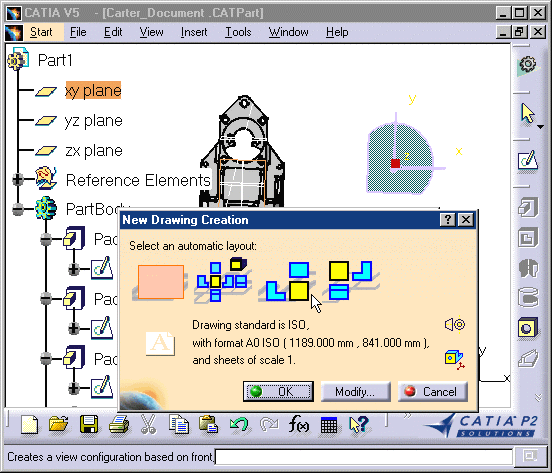
The New Drawing Creation dialog box appears with information on views that can possibly be created, as well as information on the drawing standards.

You can modify the drawing standards. To do this, click the Modify button. 
The New Drawing Creation dialog box will not appear if you did not previously open a CATPart or a CATProduct document. 
-
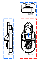
Select the views to be automatically created on your drawing from the New Drawing Creation dialog box, for example the Front, Bottom and Right icon.
-
Click OK. A progress bar appears while the views are being generated from the opened CATPart.

- a plane you possibly selected in the part.
- a planar surface you possibly selected in the part.
- xy coordinates, in case you did not open a CATPart beforehand. In this case, you will only be able to define the drawing standards via the New Drawing dialog box.
![]()