 |
This task aims at
giving you a general overview of the necessary virtual reality devices as
well as two application examples for head tracking and hand tracking. This
is the basic method requiring a manual configuration.
All the drivers supported by Version 5 can still be run as standalone
processes (as explained further in this section) but as they are now
threaded, you can also activate them using the
Immersive System Assistant
workbench which enables you to generate a configuration file containing
all the necessary data. These data will then be used to run the broker and
the driver automatically when starting Version 5. |
|
|
| |
|
|
Device Overview
|
|
Using efficiently Virtual Reality
services implies that you fully understand the Virtual Reality
architecture.
To do so, let's have a quick look at the following scheme: |
| |
 |
|
The virtual reality devices which
can be handled are connected to Version 5 through a socket communication
mechanism involving three actors: Version 5, a broker and a device driver.
Version 5 requires a broker to be able to use device drivers. A broker
is a small application holding all the running driver communication port.
This broker application always runs on the same computer as Version 5,
whereas the drivers can run on another computer or another operating
system.
Each driver declares itself to the broker thus implying that the broker
should always be running before running a driver.
Broker and driver applications can be standalone processes or run within
the Version 5 process (they are threaded processes). Some drivers may be
threaded or not, depending on the devices. As a consequence, you can use
either a threaded or standalone driver with a standalone broker.
To run a standalone broker or driver, you need to execute it explicitly,
whereas running a threaded broker or driver only requires they be activated
via the Devices tab in Tools > Options > Devices and
Virtual Reality.
Prior to using head or hand tracking in Version 5, you need to set up
these actors proceeding the following way: |
 |
-
Start the broker.
|
The broker role is to list and store any device
declaration and to provide this list to Version 5 when requested.
The broker must be started on the same host as the one of Version 5
session. |
-
Start the driver.
|
The driver will declare itself to the instantiated
broker and will answer Version 5 when an event enumeration or an
event sending is requested.
The driver may be launched on a different host as the one of the
Version 5 session.
The driver sends events to the Version 5 application. Here are
the four event types used:
- POSITION_EVENT for the tracker position and orientation in
space
- VIEWPORT_EVENT for the coordinates of the screen corners as
well as the letf and right eye position
- ButtonPress which for the press button number
- ButtonRelease for the released button number.
|
-
Start a Version 5 session.
|
When started, Version 5 asks the broker for a list
of devices and asks each device for an event enumeration. In the
meantime, these devices are asked to start or stop event sending. |
|
|
Head tracking
|
| |
There are two
kinds of head tracking:
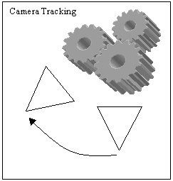
- camera tracking in which the tracking acts as if a camera
moves in the model. The displayed image is the one filmed by the camera.
In that case, the rendering projection pyramid keeps its original shape.
This tracking is typically used for head mounted display or to simulate a
camera
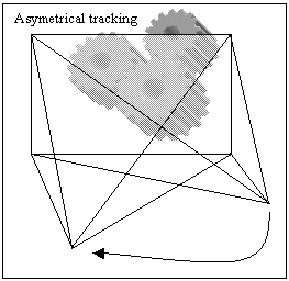
- asymetrical tracking in which an image is computed and
displayed on a screen that should be considered as being fixed in
relation to the model, although you move in relation to the screen.
This tracking is used for displaying images on fix screens and making the
user feels as if the model were steady in the room as he moves in it.
|
| |
|
 |
| |
The camera tracking functionality requires a POSITION_EVENT or a
symetric VIEWPORT_EVENT (head mounted display type).
The asymetrical tracking functionality requires a POSITION_EVENT if the
SGI multipipe management system is running, otherwise a VIEWPORT_EVENT.
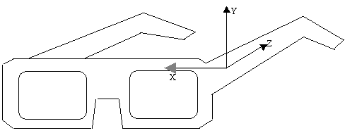
When using a POSITION_EVENT, the head tracking requires the
POSITION_EVENT X axis to be in the same direction as the vector
defined by (Left Eye, Right Eye):
|
| |
|
| |
If the tracker is not fixed on the stereo glasses so that X is well
aligned, you need to ask the driver to apply an offset matrix.
If several matching events are available, a window prompts you to
choose an event when launching the VRViewTracking command: just select
the event corresponding to the tracker dedicated to head tracking. You
can also identify the convenient event thanks to its type and emitter
driver name.
|
 |
The following
examples detail the viewpoint tracking installation procedures using a
Polhemus Fastrak sensor and an IRIX platform.
The Version 5 driver managing the Polhemus Fastrak is a standalone (i.e.
non threaded) driver named "PolExecDaemon". |
 |
-
The first step is to edit a configuration file to adapt
it to your own configuration.
| The configuration file
holds necessary information for the driver: the communication baud
rate on the serial port, the serial port number, the events to
send, the matrix you could use to virtually offset the trackers
from their mounting point, the screen definition and the eye
position for the VIEWPORT_EVENT. |
Two examples of
configuration files are detailed in this task but bear in mind that
there are no specific settings for using the Polhemus Fastrak. The
dip switch on the Polhemus box should correspond to what is
declared in the configuration file.
For your information, the settings used in Dassault Systèmes
are:Select (number of devices): Down Up Up Up (one sensor only)
I/O Select: Up Up Up Down Down Up (serial port 115200 bps).
Be careful to use always the same hemisphere during viewpoint
tracking. Refer to the Polhemus documentation for detailed
information. |
 |
The
Immersive System Assistant workbench enables you to generate
automatically the necessary configuration file for head tracking.
For detailed information, refer to
Working With the Immersive System Assistant in this guide.
However, you can still edit the configuration file manually, if
desired. To do so, follow the instructions detailed below. |
| Example 1 Let's
describe a configuration file assuming you use a Polhemus Fastrak
for tracking both head and hand. Your display system is a bench or
a multi-channel display and you use the View > Full Screen.
In this case, you need the driver to send two POSITION_EVENTs.
The
# symbol
indicates a comment in the configuration file and the opposite text
explains each of the following instructions: |
SERIALPORT
                   "COM1"

                   BPS
                   38400

                   TRACKER  0
                   POSITION_EVENT

                   TRACKER  1
                   POSITION_EVENT
#Intersense Head Tracker

                   MATRIX 0

                   [0,1,0]

                   [0,0,-1]

                   [-1,0,0]

                   [0,0,0]
#Intersense Wand

                   MATRIX 1

                   [0,1,0]

                   [0,0,-1]

                   [-1,0,0]

                   [0,0,0]
SCREEN

                   {
   UPPERLEFT  [-700,
                   300, -430]

   UPPERRIGHT [-700, 300,
                   430]

   LOWERRIGHT [-700,
                   900, 430]

                   }
|
Specify the
serial communication port number. You can use either COM1,
COM2 or COM3.
Specify the communication baud rate with the Polhemus
Fastrak. Usual baud rates are 38400 and 115200.
Here you can type as many lines as events
you need. Specify the tracker number: a Polhemus Fastrak has
up to four trackers plugged in. Specify the desired event for
each tracker. You can choose among four types of events by
selecting them using the keywords POSITION_EVENTS,
VIEWPORT_EVENT, BUTTON_PRESS and BUTTON_RELEASE. You can ask
for different events on the same tracker number.
Specify the matrix to be applied to the
POSITION_EVENT coming from tracker 0.
This matrix means that the drivers will send to the
application the Y-tracker axis as X axis, the Z-tracker axis
as Y axis and the X-tracker axis as Z axis.
If you do not apply any matrix, use an
identity matrix.
Keep a screen section (detailed hereafter) even though it is
not used.
|
|
| Now, suppose you want to
use the Polhemus Fastrak to track both hand and head without using
the MPK functionality. In this case, you will need
asymetrical tracking just as you have done it before but, as you
will not use mpconfig, you will need the driver to send a
POSITION_EVENT for the hand and a VIEWPORT_EVENT for the head.
The configuration file will then look like this: |
SERIALPORT "COM1"

                   BPS        115200

                   TRACKER 0 VIEWPORT_EVENT

                   TRACKER 1 POSITION_EVENT

                   MATRIX 1

                   [0,0,1]

                   [1,0,0]

                   [0,1,0]

                   [0,0,0]
SCREEN

                   {

   UPPERLEFT  [-700,
                   300, -430]

   UPPERRIGHT [-700,
                   300, 430]

   LOWERRIGHT [-700, 900, 430]

                   }
LEFTEYE  [0.0, 0.0,
                   61.0]

RIGHTEYE [0.0, 0.0, 124.0] |
For the
VIEWPORT_EVENT, you need to specify the corner coordinates of
the projection screens. These coordinates are to be expressed
within the same reference frame (R0) as the data sent by the
tracker.
The screen is assumed to be rectangular.
You also need to specify the eye position
in the mobile tracker reference frame.
We call "mobile tracker reference frame" the reference frame
defined by the x, y, z, h, p and r coordinates sent by the
tracker.
Express these coordinates in millimeters.
|
|
Here is some additional
information on the above-mentioned parameters:
- MATRIX
Polhemus will send an event to PolExecDaemon driver which has
been defined in the axis system of the transmitter. In turn,
PolExecDaemon will send an event to Version 5 but this event will
be modified using the matrix you applied. Generally, the matrix
is used for sending POSITION_EVENT thus, in case you are only
using VIEWPORT_EVENT, the matrix parameter is not mandatory
- SCREEN
This parameter defines the coordinates of the visualization
screen in the Polhemus axis system. The screen coordinates have
to been measured manually. The result depends on the the position
and orientation of the Polhemus transmitter.
For instance, suppose you are using a transmitter positioned in
front of the screen with X pointing out the screen, Y down and Z
right (cf. the Axis system engraved on the Polhemus transmitter
box). In this case, you get coordinates where X is constant and
negative and the other values vary along the YZ plane. This
corresponds to the values detailed in the above example:
SCREEN

               {

   UPPERLEFT
               [-700, 300, -430]

   UPPERRIGHT
               [-700,  300, 430]

   LOWERRIGHT
               [-700, 900, 430]

               }
- LEFTEYE and
RIGHTEYE
These parameters lets you define the position of the
eyes in the mobile tracker axis system. The result depends on how
the Polhemus sensor is attached to the user's head.
For instance, you can attach the Polhemus sensor to the left
branch of the steroe glasses which means that X points to the
screen, Y is up and Z goes from left eye to right eye. This
axis system corresponds to the default as explained in the
Polhemus manual (refer to the Polhemus Fastrak User's Manual
Revision F for detailed information). In that case, the eyes are
aligned exactly on the Z axis of the sensor and the coordinates
you get correspond to those detailed in the above example:
LEFTEYE [0.0, 0.0, 61.0]

               RIGHTEYE [0.0, 0.0, 124.0]
These coordinates have to be measured manually.
|
| Example 2 Let's
take a look at a second example and consider the following case:
you want to use the Polhemus Fastrak to track both hand and head
and your display system is a Head Mounted Display.
You will thus need a camera type tracking. You also need the driver
to send a POSITION_EVENT for the hand and either a POSITION_EVENT
or a VIEWPORT_EVENT for the head. If the driver sends a
POSITION_EVENT for the head, no stereo viewing is available and you
need to adjust the viewpoint angle for your head mounted display in
Version 5. To do so, create a named view by selecting View >
Named Views then edit its properties.
Note: you cannot adjust its ratio in case the head mounted
display optics are not symmetric. |
 |
This
camera is saved in the .CATProduct file under the application node.
The POSITION_EVENT must have its X axis going to the right, its Y
axis up and its Z axis backwards.
Otherwise (as we explained it before), you have to ask the driver
to apply a rotation matrix. You can use the first configuration
file for this system. |
| If you use a
VIEWPORT_EVENT, the configuration file should be as follows: |
                   SERIALPORT
                   "COM1"

                   BPS
                   115200

                   TRACKER
                   0
                   VIEWPORT_EVENT

                   TRACKER
                   1
                   POSITION_EVENT

                   MATRIX 1

                   [0,0,1]

                   [1,0,0]

                   [0,1,0]

                   [0,0,0]
HMDSCREEN

                   {

   UPPERLEFT  [700,
                   -900, -720]

   UPPERRIGHT [700,
                   900, -720]

   LOWERRIGHT [700, 900,
                   720]

                   }
                   LEFTEYE  [0.0, 0.0, 61.0]

                   RIGHTEYE [0.0, 0.0, 124.0]
|
Use this section
to describe the HMD fields of view. Describe the desired
virtual projection pyramid.
All the figures are to be expressed in the
mobile tracker (fixed on the head) reference frame centered
between right and left eye. For instance, if the tracker is
mounted such as Z is going down and Y forward, the
coordinates are as shown below:
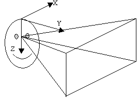 |
| Here, the pixel ratio is
1.25. |
|
|
 |
Pay attention to the coordinates you enter. The
more careful you are, the better the results will be. |
-
Run the Virtual
Reality broker using the following command:
/.../Bn/Os_a/code/command/catstart -run
             CATVisVRBroker
where:
/.../ is the Version 5
installation pathn is the current release numberOs_a is:
For a standard installation, the path should be
/usr/DassaultSystemes. |
-
Run the tracker device driver for viewpoint tracking:
             /.../Bn/Os_a/code/command/catstart -run PolExecDaemon -object
             computer_name configuration_file
where
"configuration_file" is the full path name of the configuration
you edited in step 1 and "computer_name" is the name of the
computer. |
 |
This driver may be used with any device
compliant with the Fastrak protocol. |
-
Start Version 5:
/.../Bn/Os_a/code/command/catstart |
| If you want to use stereoscopic viewing, you have
to perform Steps 5 to 12 otherwise, jump to Step 13. |
-
Select Tools > Options > General >
Display then click the Visualization tab.
-
In the Stereo enable area, click On.
-
Click OK to validate your parameters.
-
Restart Version 5.
-
In the power input box, enter the following command:
-
Click OK.
-
In the power input box, enter:
|
c:VRViewTracking
The Viewpoint Tracking is activated. It can be simply
deactivated by re-entering the c:VRViewTracking
command in the power input field |
 |
Before using this command, make
sure that a driver is running and able to send POSITION_EVENT or
VIEWPORT_EVENT. |
|
| |
Intersense
|
| |
Since the Intersense firmware protocol is an enriched Fastrak
protocol, the PolExecDaemon Version 5 driver can communicate with an
Intersense IS900 tracker.
The above-mentioned instructions are still valid in this case.
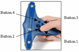
In addition, the Intersense IS900 supports a Wand hand tracker. This
specific hand tracker has four buttons the driver is able to decode as
ButtonPress and ButtonRelease events.
|
| |
|
| |
To configure the driver with these two events, use the keywords
BUTTON_PRESS and BUTTON_RELEASE as explained above.
Use the following matrix in the PolExecDaemon driver so that the
attached reference frame is as required by the Version hand tracking
functionality:
MATRIX 1

       [0,1,0]

       [0,0,-1]

       [-1,0,0]

       [0,0,0]
|
| |
Ascension Flock
of Birds
|
| |
The Ascension Flock of Birds tracking system driver is now supported
for head tracking on Windows and UNIX. Note that from V5R13 onwards, you
do not need to install the Bird.dll library anymore.
This driver allows to measure in real time the position and orientation
of several bodies in space. It can be used as a standalone executable
(called "CATFlockOfBirdsDriver") or as a threaded driver.
To use this driver as a standalone process, follow the instructions
below:
On Windows
Go to the following installation directory
\install_root\intel_a\code\bin
and enter the command:
catstart -run CATFlockOfBirdsDriver [-f Frequency] [-com
       SerialPortNumber] [-bps SerialPortSpeed] [-host BrokerHostName] [-m
       TransformationMatrix] [-n NumberofDevices] [-mouse DeviceNumber]
On UNIX
Go to the following installation directory
/install_root/OS_a/code/bin
where "OS_a" is:
and enter the command:
./catstart -run CATFlockOfBirdsDriver [-f Frequency] [-com
       SerialPortNumber] [-bps SerialPortSpeed] [-host BrokerHostName] [-m
       TransformationMatrix] [-n NumberofDevices] [-mouse DeviceNumber]
Below is a description of the arguments:
|
-f |
Event sending frequency from the CATFlockOfBirdsDriver
to the Version 5 session.
If not specified, a default value of 100 Hz is used |
|
-com |
Serial port number to which the Flock of Birds is
connected.
If not specified, a default value of 1 is used, meaning "COM1" on
Windows systems. |
|
-bps |
Serial port speed.
If not specified, the driver tries to connect to the Flock of Birds
at the speed of 115200 bps. |
|
-host |
Name of the host on which the CATVisVRBroker is
running.
If not specified, LocalHost is assumed. |
|
-m |
Position and orientation received from the Flock of
Birds are multiplied by this matrix before being sent to the Version
5 session. The matrix should be described in lines using the
following format:
-m [m11,m12,m13][m21,m22,m23][m31,m32,m33]
If not specified, the Identity matrix is assumed. |
|
-n |
Number of Flock of Birds running at the same time.
If not specified, one Flock of Birds is assumed. |
|
-mouse |
Device number of the Flock of Birds to which an
Ascension 6D Mouse is connected.
If not specified, no 6D Mouse is supposed to be used. The numbering
of the devices start with number 1. |
|
-debug |
Activates the display of error messages. |
However, bear in mind that this driver sends POSITION_EVENT only.
This driver is also supported for
hand tracking.
|
| |
ART Optical
tracking system
|
| |
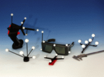
Version 5 now supports the ART driver. This driver can be used as a
standalone executable (called "CATARTDriver") or as a threaded driver.
|
| |

|
| |
How does it work?
The ART Optical tracking system sends position and button information at
a specific TCP/IP address on a specified port number. The Version 5
driver reads this ethernet port and decode the information before
translating it. The translated information is then sent by the driver to
the Version 5 session in a Version 5 format.
To use this driver as a standalone process, enter the following
command:
On Windows
installation_path\intel_a\code\command\catstart -run
       CATARTDriver -h
The "-h" option displays help information.
On UNIX
/install_path/OS_a/code/command/catstart -run
       CATARTDriver -h
where "OS_a" is:
Note that this driver sends:
- POSITION_EVENT
- BUTTON_EVENT
- SLIDER1_EVENT
- SLIDER2_EVENT.
This driver is also supported for hand
tracking.
|
|
 |
|
Hand tracking
|
| |
The following two
examples are designed for hand tracking using:
- a Joystick Spacestick VirtualPresence with a Polhemus sensor and the
DMU Navigator 3 product
- a FakeSpace Neowand.
|
| |
Note that the
Immersive Assistant workbench
enables you to generate automatically the necessary configuration file for
hand tracking.
However, you can still edit this file manually if desired. To do so, follow
the instructions detailed below. |
| |
The VR Cursor command switches
on and off the hand tracking functionality with the following prerequisite:
one or more drivers should be running and able to send a POSITION_EVENT, a
ButtonPress and a ButtonRelease. The command will look for the first driver
able to send POSITION_EVENT then, ButtonPress and ButtonEvent.
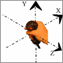
The POSITION_EVENT used for hand tracking should have its X axis
pointing to the right, its Y axis up and its Z axis backward as shown
below: |
| |
|
| |
If the tracker is
not fixed this way in the hand device, you will have to ask the driver to
apply an offset matrix.
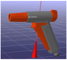
When "On", hand tracking displays a red laser pointer. This pointer is
collocated with the hand tracker so that you really feels the pointer
getting out of your hand.
This feeling is reinforced in stereoscopic display: |
| |
|
| |
The buttons enable
you to pick within the model and to manipulate the viewpoint.
There are two manipulation modes: Examine mode
and Fly mode. You can switch between
the two simply by running the VRFly command. The Examine mode is
the default mode when running the VRCursor command.
You can also move the model objects by snapping the 3D compass to them.
The 3D compass will then follow your hand moves.
Note: setting the compass to "Snap automatically to selected object"
lets you snap the compass to any objects you can pick with the laser
pointer.
Now let's go to using hand tracking!
|
| |
Joystick Spacestick |
 |
-
Run the
PolExecDaemon.
-
Run the Joystick3DExecDaemon using the following command:
             /.../Bn/{OS_a}/code/command/catstart -run "Joystick3DExecDaemon
             brokerHost serialPort"
where
- n is the current release number
- /.../ is the Version 5 installation
path. For a standard installation, the path should be
/usr/DassaultSystemes/
- {OS_a} is the name of your operating system (aix_a,
etc.)
- brokerHost is the name of the computer on
which the device broker and Version 5 are running
- serialPort is the port to which the
joystick is connected (e.g.: COM1, COM2, COM3 or COM4).
There is no configuration file for this driver. |
 |
Another method to run the
driver is to first create an icon on your desktop, then drag the
Joystick3DExecDaemon.exe file from the explorer and drop it onto
the desktop (this file can be found in the installation directory,
in intel_a\code\bin).
Edit the icon properties and modify the target file to c:\...\intel_a\code\bin\Joystick3DExecDaemon.exe
brokerHost serialPort.
Then, you just have to double-click the icon to run the driver. |
-
For the Polhemus version (a Polhemus tracker is fixed
inside the joystick), use the following matrix in the PolExecDaemon
driver so that the attached reference frame matched the Version 5 hand
tracking functionality requirements:
MATRIX

             [0,0,1]

             [1,0,0]

             [0,1,0]

             [0,0,0]
The buttons are located as described on
the picture below: |
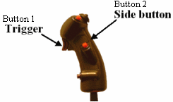 |
-
Run the DMU Immersive Review configuration then the DMU
Navigator 3 product.
|
| |
Fakespace
Neowand |
| |
The Version 5
driver managing the Fakespace Neowand buttons is a standalone (i.e. non
threaded) driver named "CATNeoWandDriver". |
 |
-
Run the CATNeoWandDriver using the following command:
             /.../{OS_a}/code/command/catstart -run CATNeoWandDriver brokerHost
             serialPort"
where
- /.../ is the Version 5 installation
path. For a standard installation, the path should be
/usr/DassaultSystemes/Bn ("n" representing
the release number)
- {OS_a} is the name of your operating system (aix_a,
etc.)
- brokerHost is the name of the computer on
which the device broker and Version 5 are running
- serialPort is the port to which the
joystick is connected (e.g.: COM1, COM2, COM3 or COM4).
There is no configuration file for this driver. |
 |
Another method to run the
driver is to first create an icon on your desktop, then drag the
CATNeoWandDriver.exe file from the explorer and drop it onto the
desktop (this file can be found in the installation directory, in
intel_a\code\bin).
Edit the icon properties and modify the target file to c:\...\intel_a\code\bin\CATNeoWandDriver.exe
BrokerHostName serialPort.
Then, you just have to double-click the icon to run the driver. |
-
In case a Polhemus tracker is fixed inside the NeoWand,
use the following matrix in the PolExecDaemon driver so that the attached
reference frame matches the Version 5 hand tracking functionality
requirements:
MATRIX

             [0,1,0]

             [0,0,-1]

             [-1,0,0]

             [0,0,0]
The buttons are located as shown in the picture below: |
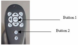 |
Click the thumbnail
 to enlarge the picture.
 |
|
| |
Icido Thready
Motion Controller |
| |
In addition to the
Fakespace Neowand, Version 5 supports Icido Thready Motion Controller (also
known as "Mike"). The driver managing this device is named "CATMikeDriver"
and should be used the same way you do with CATNeoWandDriver detailed
above. |
| |
Ascension Flock
of Birds |
| |
The Ascension Flock of
Birds tracking system driver is now supported for hand tracking on Windows
and UNIX. Note that you do not need to install the Bird.dll library
anymore.This driver allows to measure in real time the position and
orientation of several bodies in space. It can be used as a standalone
executable (called "CATFlockOfBirdsDriver") or as a threaded driver. To
use this driver as a standalone process, follow the instructions below:
On Windows
Go to the following installation directory
\install_root\intel_a\code\bin
and enter the command:
catstart -run CATFlockOfBirdsDriver [-f Frequency] [-com
     SerialPortNumber] [-bps SerialPortSpeed] [-host BrokerHostName] [-m
     TransformationMatrix] [-n NumberofDevices] [-mouse DeviceNumber]
On UNIX
Go to the following installation directory
/install_root/OS_a/code/bin
where "OS_a" is:
and enter the command:
./catstart -run CATFlockOfBirdsDriver [-f Frequency] [-com
     SerialPortNumber] [-bps SerialPortSpeed] [-host BrokerHostName] [-m
     TransformationMatrix] [-n NumberofDevices] [-mouse DeviceNumber]
Below is a description of the arguments:
|
-f |
Event sending frequency from the CATFlockOfBirdsDriver
to the Version 5 session.
If not specified, a default value of 100 Hz is used |
|
-com |
Serial port number to which the Flock of Birds is
connected.
If not specified, a default value of 1 is used, meaning "COM1" on
Windows systems. |
|
-bps |
Serial port speed.
If not specified, the driver tries to connect to the Flock of Birds
at the speed of 115200 bps. |
|
-host |
Name of the host on which the CATVisVRBroker is
running.
If not specified, LocalHost is assumed. |
|
-m |
Position and orientation received from the Flock of
Birds are multiplied by this matrix before being sent to the Version
5 session. The matrix should be described in lines using the
following format:
-m [m11,m12,m13][m21,m22,m23][m31,m32,m33]
If not specified, the Identity matrix is assumed. |
|
-n |
Number of Flock of Birds running at the same time.
If not specified, one Flock of Birds is assumed. |
|
-mouse |
Device number of the Flock of Birds to which an
Ascension 6D Mouse is connected.
If not specified, no 6D Mouse is supposed to be used. The numbering
of the devices start with number 1. |
|
-debug |
Activates the display of error messages. |
However, bear in mind that this driver sends POSITION_EVENT only. |
| |
ART Optical tracking system |
| |
Version 5 now
supports the ART driver for hand tracking. This driver is also supported
for head tracking. |
|
 |
| |
Tracking
calibration |
| |
In case you intend to use a multi-channel display system with head
tracking, you should add some information related to the tracking sytem
inside the MPK configuration file. These information should be added at the
end of the file, before the last closing bracket "}".
They should all begin with a comment symbol "#". Even though there are
commented out, they are used by Version 5. The only used information are
those included in the "userdata" section. The measure unit for all the
numbers it the millimeter.
As required by the head tracking functionality,
the mobile tracker reference frame should have its X axis pointing right,
its Y axis pointing up, and its Z axis pointing backward. However, it may
not have its origin located exactly between the two eyes. The
"eye-offset" keyword enables you to specify the middle eye point
coordinates in this mobile tracker reference frame.
The fix tracker reference frame may be different from the MPK frame. Use
the "tracker-X", "tracker-Y" and "tracker-origin" keywords to specify it.
In the example below, the fix tracker frame has its X axis pointing
backward., its Y axis pointing to the right and its origin directly 1524 mm
under the MPK origin.
If you used the millimeter as unit in the MPK file, the keyword
"MPK_unit_in_mm" should be valuated to 1. If you used meter for instance,
it should be valuated to 1000. |
| |
# All dimensions are to be specified in mm.
# - eye-offset specifies the eye coordinates in the mobile tracker
     frame
# - IPD is the inter-pupillary distance
# - the tracker related data describe the fixed tracker frame in the
     MPK global frame
# - MPK_unit_in_mm defines the MPK data unit.
# userdata
# {
#
     eye-offset
     [0,-20,0]
#
     IPD
     57
#
     tracker-X
     [0,0,-1]
#
     tracker-Y
     [1,0,0]
#
     tracker-origin
     [0,-1524,0]
#
     MPK_unit_in_mm
     1
|
| |
A standard session
example |
 |
Suppose the following
case:
- you use a three-channel display system in a reality center
- you also use a three-pipes SGI computer. The display system has three
projectors, one per channel, projecting active stereo
- you want your head and hand to be tracked in front of the screens
- your tracking system is an Intersense IS900
- there are two trackers, one for the head and one for the hand, both
plugged on the IS900
- the hand tracker is an Intersense wand with four buttons.
You have already set up the system, i.e. you have all the necessary
configuration files and your CATSettings are up-to-date.
Moreover, you have set the Virtual reality starting mode option
to Manual in Tools > Options > General > Devices
since the Intersense driver is a standalone, i.e. non threaded, driver.
The scenario detailed hereafter shows you how to use the system. |
 |
-
Power up the Intersense IS900
-
Open a shell window then run the broker (this is a non
threaded case)
-
Open another shell window then run the Version 5 IS900
driver. Because of the configuration file you use, the driver will send
two POSITION_EVENTs (one per tracker), a ButtonPress and a ButtonRelease
-
Open a third shell window then run a Version 5 session
-
Open a .CATProduct model file
-
Switch to Full Screen mode by selecting View > Full
Screen.
-
Key in the following command in the power input box:
c:VR View Trackingthen choose the
head tracker POSITION_EVENT before clicking OK. |
-
Key in the following command in the power input box:
-
Key in the following command in the power input box:
c:VRFlyto select the convenient
manipulation mode for your session |
-
Select View > Full Screen.
The system is running.
|
 |
| You can customize the commands
entered in the power input box so that they appear as push buttons
in a toolbar. You can also assign a keyboard shortcut to them if
you wish so. |
|
| |
When you want to open
a new model or quit the session:
-
Deactivate the full screen mode and stop the multipipe
management by right-clicking then deselecting Full Screen
-
Key in c:VR View Tracking in the power input
field to stop head tracking
-
Key in c:VR Cursor in the power input field
to stop hand tracking
-
Select File > Open or File > Exit.
|
|
 |
![]()
