 |
In this task, you will learn how
to access and use the Immersive System Assistant workbench in
order to configure your Virtual Reality devices and display system.
Within this workbench, the various elements (screens, trackers, etc.)
any reality center hardware installation is made of are graphically
represented and this visual feedback enables you to create, edit and delete
very easily the necessary data.
These data will then be used to generate automatically an XML
configuration file via a command provided by the Immersive System
Assistant workbench, thus avoiding a "painful" manual edition.
All drivers and brokers supported by Version 5 are threaded which means
that there is no need to run external processes anymore.
In addition to that, all the necessary MPK display configuration data
(including those related to the threaded brokers and drivers) are now
grouped together into a single
configuration file saved in XML format. These data will then be used
when starting up your Version 5 session to run the broker and the driver
automatically with the appropriate configuration.
However, note that you can still run drivers and brokers manually as
before if needed, for instance when using external drivers or when running
a driver on a remote computer.
|
 |
-
Access the Immersive System Assistant
workbench by selecting the Start > Infrastructure >
Immersive System Assistant
 .
The Immersive System Assistant workbench opens: .
The Immersive System Assistant workbench opens:
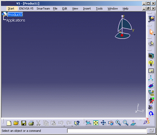 |
This workbench lets you create and manipulate
several types of objects:
- graphic board (or IG for "image generator")
- window
- view (either screen or camera)
- head
- hand picking device
- tracking station
- tracker.
Note that the head, the hand picking device and the trackers are
automatically managed and thus, cannot be deleted. |
-
Click
New IG
 to create a graphic board (you can modify the default name by entering a
new name in the Display box):
-
Click
Toggle the plan view on
 to display the graphic board symbol in the current window.
| You can then hide the graphic board by clicking
again this icon. |
-
Repeat steps 2 and 3 to create another graphic board and
display it in the current window. The geometry area now looks like this:
-
You
are now going to create a rendering specification using
New View
 .
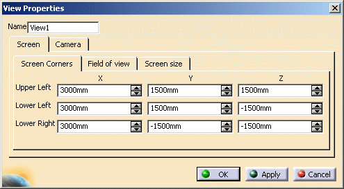
This opens the View Properties dialog box which lets you
define the type of view you wish to use as well as its properties: .
This opens the View Properties dialog box which lets you
define the type of view you wish to use as well as its properties:
 |
You can choose between a
screen view or a camera view:
- screen: use it when the viewpoint to render is defined by the
user moving in front of a fixed screen
- camera: use it when the viewpoint to render is attached to
the head of the user, like a camera (such as a head-mounted
display).
|
|
Screen View |
1. Click the tab you will
use to set the screen properties, either:
- Screen Corners
Enter the coordinates of three screen corners (upper left
corner,
lower left corner and lower right corner)
- Field of view
|

|
The H fov and V fov boxes represent the
horizontal and vertical field of view (in degrees), respectively.
The H shift and V shift boxes let you
translate the screen horizontally and vertically.
The Head box defines the horizontal rotation of the
screen around the head.
The Pitch box defines the vertical rotation of the
screen around the head.
The Distance box defines the distance (in millimeters)
to the head.
|
|

|
The Width and Height boxes correspond to
the screen width and height, respectively.
The Head box defines the horizontal rotation of the
screen around the head.
The Pitch box defines the vertical rotation of the
screen around the head.
The Center area lets you set the coordinates of the
screen center.
|
 |
Once you entered values in
a tab, the values of the two other tabs are automatically updated
accordingly. You can then pass from one tab to another very easily. |
|
Camera View |
|
1. Click the Frustum tab: |

|
"Frustum" is a truncated pyramid representing the angular
definition of the field of view for a distance equal to 1. Enter
the desired values in millimeters for Left, Right,
Top and Bottom.
|
| 2. Click the Field of
view tab: |

|
The H fov and V fov boxes represent the
horizontal and vertical field of view (in degrees), respectively.
The H shift and V Shift boxes let you
translate the screen horizontally and vertically.
|
-
Click OK when
satisfied with your screen definition.
-
Repeat steps 5 and 6 to create another screen view.
 |
You can modify the
screen properties at anytime by double-clicking the screen in the
geometry area or in the specification tree. |
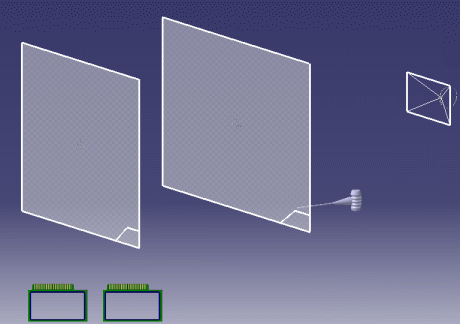
| The result looks something
like this (depending on the values you enter): |
 |
-
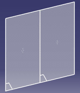
Click
Snap
 to snap one of the screens to the other. To to so, select an edge of the
screen to be snapped then an edge of the other screen:
 |
| You can also snap the 3D compass to a screen view
to manipulate it very easily as shown below: |
|
|
| Note that the compass cannot be snapped to camera
views. |
|
The next step is to render the specifications in a
window.
A window can be defined as an OpenGL rendering zone
for a defined viewpoint and is located in the graphic board frame
buffer. The specification of the viewpoint to render in a window is
called a "view". As a consequence, each window points to a view,
either a screen view or a
camera view depending on the
viewpoint to render. |
-
Click New Window  to open the Window Properties dialog box:
-
Give a name to the new window (or leave the default name)
and set is as your referenced window by clicking the Main Window
option.
|
The main window is the window which is always
visible in Version 5 (the other windows being created "on the fly"
when you run View > Full Screen). |
-
Select the associated graphic board in the geometry area
or in the specification tree. The IG box ise automatically
updated accordingly.
-
Select the view the window will point to. The View
box will be automatically updated accordingly.
-
In the Viewport area, indicate the portion of the graphic
board you are going to use. To do so, enter the desired coordinates in
the Left, Top, Width and Height
boxes.
|
"0.00" means the view is located in top left
corner
"1.00" means the view is located in bottom right corner. |
 |
 |
| Default window
Left = 0.00
Top = 0.00
Width = 1.00
Height = 1.00 |
User-defined window
Left = 0.33
Top = 0.15
Width = 0.57
Height = 0.68 |
|
-
Specify the Rendering Mode:
-
Mono: only the cyclop viewpoint is rendered
-
Left and Right eye: these modes are used for
passive stereo display systems in which left eye and right eye
images are displayed simultaneously on the screen. Image
separation is performed by filtering glasses using polarized
light, for instance
-
Active Stereo: left eye and right eye images are
alternatively displayed on the screen at twice the refresh rate.
An active pair of glasses with two shutters working in
synchronization with the images is needed. Synchronization is
often achieved using an infrared emitter: the left eye shutter is
closed when the right eye image is displayed, and reciprocally.
|
-
Use the Mirror Mode box if you want to create
a symmetry and define the axis with respect to which the reflected image
should be inverted.
|
Note that you can also create a symmetry using the
projector. |
-
Click Apply then
OK to validate and close the dialog
box.
| Now let's go to modifying the head properties! |
-
Double-click either the
head in the geometry area or the Head item in the specification tree to
open the Head edition dialog box:
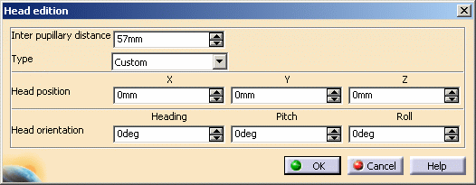 |
- indicate the distance (in millimeters) between left eye and
right eye in the Inter pupillary distance box
- the Type box is relevant only when working with
devices such as trackers
- define the Head position (in millimeters) along X,
Y and V axes
- define the head orientation in the Heading box
- set the vertical rotation of the head in the Pitch
box
- set the horizontal rotation of the head in the Roll
box.
The head position and orientation you define in this dialog box
correspond to the default head position and orientation relative to
the screens when the head is not tracked. |
-
Click OK to validate.
| If you do not use trackers, it is now time to
generate your configuration file. For those who use trackers, a
few additional operations need to be carried out before generating
the configuration file. Skip the steps below and jump to step
24. |
-
Click
Configure VR System
 .
The following dialog box appears: .
The following dialog box appears:
-
Click OK to validate
and close the Generate VR Configuration dialog box.
|
The XML file is generated and saved in the
directory you specified. A warning message informs you that you
need to restart your session to take this modification into
account. |
-
Exit your Version 5 session.
-
Restart a Version 5 session which is now correctly
configured.
-
Switch to Full Screen mode by selecting View > Full
Screen.
|
You are now ready to start! |
| If you want to use
trackers, here are the additional steps you need to follow: |
-
Click
Create New Tracking Station
 to create the tracking station your trackers will be associated to and to
define the type of tracker to be used.
The Tracking Station Properties dialog box opens:
-
Type a Name (or leave the default) then
specify the Type of the driver you intend to use (either
Polhemus or IS900), serial communication Port number
the driver is connected to as well as the communication Baud Rate
on the serial port.
|
You can now choose a Flock of Birds or ART driver
in the Type list. |
 |
If you choose a Version 5 compatible driver of your
own (i.e. a "Custom" type), a new box appears to the right asking
you for the corresponding daemon name. |
-
Indicate the Position of the tracking station.
-
Indicate the tracking station:
- orientation in the Heading box
- vertical rotation in the Pitch box
- horizontal rotation in the Roll box.
|
-
In the Trackers area, identify the trackers to be
connected to the tracking station by checking the corresponding figure.
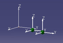
| Once you validated the tracking station definition,
the tracking station and the trackers it is associated to are
displayed in the geometry area. In our example, we created a
tracking station with two trackers: |
 |
-
Double-click the head in the geometry area or the Head
item in the specification tree to open the Head edition dialog
box then specify the head type.
| The next step is to edit the tracker. To do so: |
-
Double-click the tracker symbol in the geometry area or
the number of the tracker you wish to edit in the specification tree.
This opens the Tracker Edition dialog box:
-
Select the Tracked Element from the pull-down
list. The tracker may be attached to the head, the hand or another
device.
 |
When several trackers are
associated to the tracked element, activate the Viewpoint
Manager option to indicate which tracker will be used.
For hand tracking, this option is named Picking Manager. |
| A tracker may be set as
Button Manager when this tracker can also be used as a
button device (for instance the IS900 or the ART tracker). Checking
this option means that the button device will be used by the
VRCursor
command. |
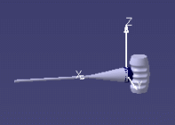
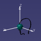
| When the tracked element is
selected, the tracker is attached to the corresponding element
symbol in the geometry area and the color of the sphere changes
according to the type of tracking: |
 |
 |
|
Hand tracking |
Head tracking |
|
-
If you are tracking hand or head, click the
 button to automatically generate the matrices and set the standard, i.e.
right, position for the tracker depending on the type of tracking station
and tracked element.
|
The tracker symbol may be grayed out and dotted if
the matrices can be automatically calculated and if the information
you entered does not match those we recommend.
If you want to define by yourself the tracker
position, jump to the next step. |
-
If you choose a "custom" tracker, the position and
orientation data define the virtual tracker viewed by Version 5. These
data correspond to the offset of the virtual tracker in relation to the
physical tracker.
|
The
 button is activated to let you define the tracker position in the
device as well as its orientation:
- the Heading box lets you define the tracker
orientation
- the Pitch box lets you define the vertical
rotation
- the Roll box lets you define the horizontal
rotation.
|
-
Click
New Button Device
 to access the Button Device Properties dialog box:
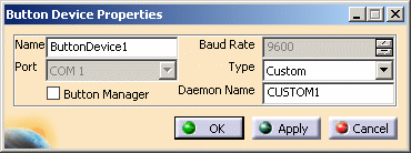 |
Specify the following information:
- enter the name of the button device in the Name
box
- select the device type in the Type list: CUSTOM,
Mike, NeoWand or SpaceStick
- indicate the Daemon name.
- Button Manager: check this option if you want the button
device to be used by the
VRCursor
command.
This capability is relevant for hand button devices onto which a
tracker has been fixed, such as the Fakespace Neowand, the
Virtual Presence SpaceStick, the ICIDO Mike, etc. In that case,
you need to define a button device independently from the
tracker.
|
-
Generate the configuration files by clicking
Generate Configuration Files
 .
For detailed information, refer to step
19 and repeat steps 19 to 22. .
For detailed information, refer to step
19 and repeat steps 19 to 22.
-
The next step depends on the driver and broker you are
using:
-
if you are using a non-threaded broker and
driver, you need to run them manually using the generated XML
configuration file. The broker must be run first then, the
driver. For detailed information on the commands to run, refer to
Head Tracking or
Hand
Tracking according to the type of tracking you want to
perform.
Then, you can restart a Version 5 session
-
if you are using a threaded broker and driver,
you can directly restart a Version 5 session: the driver is
automatically run with the appropriate configuration.
|
-
In your
Version 5 session, click Test viewpoint and VR
cursor tracking
 to test either hand or head tracking, or even both if needed.
| The Test tracking window appears and
indicates for which tracking the current session is configured. |
-
Specify the type of tracking you want to test (if your
session is configured for both head and hand tracking) then click
Start to validate.
| As you use your tracking device, the tracker
representation will move accordingly on screen. |
|