 |
-
Click the Break Surface or Curve icon:

| The Break dialog box and the
Tools Palette appear. |
-
Click the Break Surfaces option:

| The Break dialog box content has been
modified according to the selected type. |
 |
|
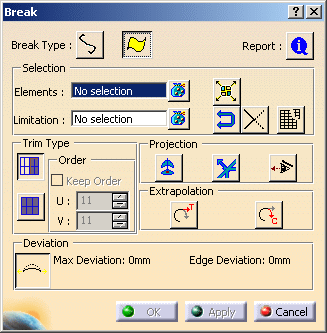
The Break dialog box displays the following
information:
-
Trim Type:
-
 Face Trim: surfaces are topologically relimited and the
control points of the initial surfaces are kept.
-
 Surface Trim: surfaces are geometrically relimited and the
control points of the resulting surfaces are kept.
Only 4
edge-patches are created with Surfaces by curves option.
-
Order
-
U: defines the U
order.
Available only with Break Surfaces and Surface Trim options.
The U and V order maximum values are set with the
Order setting option of the FreeStyle settings.
-
V: defines the V
order.
Available only with Break Surfaces and Surface Trim options.
The U and V order maximum values are set with the
Order setting option of the FreeStyle settings.
-
Projection: By default the points
that do not lie on the trimmed elements will not be projected onto the
trimming elements.
-
 Along Compass:
projects along the compass direction.
-
 Along Normal: projects along the normal direction.
-
 Along Viewing Direction: projects along the viewing
direction.
-
Extrapolation:
-
 Tangential Extrapolation: extrapolates along the tangent
direction.
Available only with Break Surfaces option.
-
 Curvature
Extrapolation: extrapolates along the curvature direction.
Available only with Break Surfaces option.
-
 Report:
displays a status about cutting elements:
-
Cutting elements that can be used for the
Break (marked by a green tip). When you click on the text, the
corresponding curve is highlighted in green in the 3D geometry.
-
Cutting elements that cannot be used for the
Break (marked by the condition to be applied so that they can be used:
projection, etc). When you click on the text, the corresponding curve
is highlighted in red in the 3D geometry.
-
When there is no selection of cutting
elements, an error message is issued and the Break Report
panel informs you that no element is selected.
-
When a red cross is displayed, it means
that the problem cannot be managed by the application.
-
Max deviation: displays the
maximal deviation between original surface and the resultant surface in
the dialog box and on the geometry.
Available only with Break Curves and Trim Surface
options.
|
-
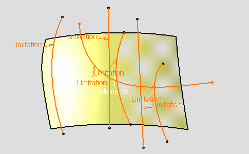
Select the surface.
-
Select the Cutting field in the Break
dialog box and select the six curves as shown.
-
Click Apply in the Break dialog
box.
| The surface has been trimmed. By default, only one trimmed
element is kept (no transparency has been applied) other not (a
transparency has been applied). |
 |
-
Click the curve segment to be kept: it
appears with no transparency in the 3D geometry.
-
Right-click any relimited element to display the
following contextual menu.
 |
-
Keep all: all parts of the all
curves are kept.
-
Keep all but this: all parts of all
curves are kept except the selected one.
-
Remove all but this: all parts of
all curves are removed except the selected one.
|
|
To keep, or do not keep, some elements press the Ctrl key and click them. |
-
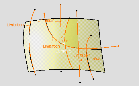
Click the Along Compass option:

-
Click Apply in the Break dialog
box.
| Elements that do not lie on the trimmed elements
will be projected (pseudo-intersections) onto the trimming elements
according to the compass direction. |
 |
-
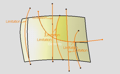
Click the Along Normal option:

-
Click Apply in the Break dialog
box.
| Elements that do not lie on the trimmed elements
will be projected (pseudo-intersections) onto the trimming elements
according to the normal direction. The surface has been trimmed. |
 |
-
Click the Shorten Mesh option:

-
Click Apply in the Break dialog
box.
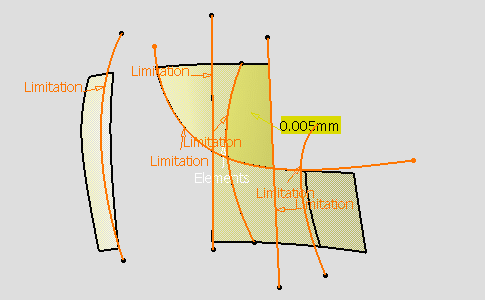
- The maximal deviation is displayed in the Break
dialog box and on the geometry (yellow label).
- The maximum degree variation allowed for each
patch of the new surface as compared to patches of the initial surface can
be modified.
- Click the U Order and the V Order text
to edit and modify the values (besides is an example with U and V values
set to 8).
|
 |
-
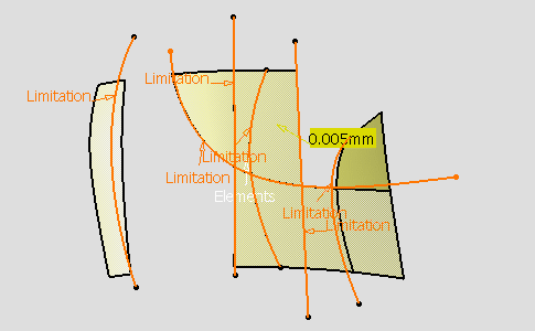
Click the Tangential Extrapolation option:

-
Click Apply in the Break dialog
box.
| As a consequence, one edge is added. |
 |
-
Click OK in the Break dialog box.
|
![]()