 |
-
From the Start>Knowledgeware menu, access the
Business Process Knowledge Template workbench.
-
Create the Table technological type.
-
Click the Table technological object and click the
Sequential Combination behavior ( )
to create a combination of behaviors. )
to create a combination of behaviors.
 |
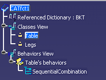
At this stage of the scenario, your feature
dictionary is similar to the graphic opposite.
|
 |
-
Double-click the SequentialCombination in the Behaviors
View and Table in the Behaviors tab to access the sequential combination.
-
Double-click the SequentialCombination node that is
displayed in the Behaviors tab. (Expand the Table node if need be.)
-
Enter the name of the combination, Creating the slab
in this scenario, in the Name field of the opening dialog box
and click OK to validate.
-
Click the Creating the slab combination in the
Behaviors tree and click the Load Behavior icon ( ). ).
-
Click the Creating the slab combination in the
Behaviors tree and click the Bind Object Behavior icon ( ). ).
-
Double-click the BindObject behavior. The Bind Object
window is displayed. Enter ../../.. in the Relative Name field. Click
OK to validate.
-
Click the Creating the slab combination and
click the Insert Components Behavior icon ( ).
An InsertComponents behavior is displayed in the Behaviors tab. ).
An InsertComponents behavior is displayed in the Behaviors tab.
- In the Definition scrolling list, select Existing Component.
|
- Click the Existing component field, expand the LoadDocument
variables node and select the output Document. =LoadDocument\Document
is displayed in the Existing component field.
|
- Click the Father product field, expand the BindObject
variables node and select the output link. =BindObject\Link
is displayed in the Father product field.
|
|
|
-
Click the Table type and click the Sequential
Combination behavior ( )
to create a combination of behaviors. )
to create a combination of behaviors.
-
Double-click the SequentialCombination node that is
displayed in the Behaviors tab. (Expand the Table node if need be.)
-
Enter the name of the combination, Creating the legs
in this scenario, in the Name field of the opening dialog box
and click OK to validate.
-
Click the Creating the legs combination in the
Behaviors tree and click the Filter Catalog Behavior icon ( ). ).
-
Double-click the FilterCatalog node. The Filter Catalog
editor is displayed.
- Click the ... button and select the
BktLegsCatalog.catalog
in the File Selection dialog box and click Open when
done.
|
|
|
-
Click the Creating the legs combination and
click the Generate Components Behavior icon ( ). ).
-
Double-click the Generate Components behavior. The
GenerateComponents dialog box is displayed.
- In the Name field, enter Generate legs.
|
- Click the Component list name, expand the Table variables
node and select the Legs_list attribute: The other fields are
automatically filled.
|
|
|
-
Click the Generate legs combination and click
the Bind Object Behavior icon ( ). ).
-
Double-click the BindObject behavior. The Bind Object
window is displayed. Enter ../../.. in the Relative Name field. Click
OK to validate.
-
Click the Generate legs combination and click
the Instantiate Template behavior icon ( ).
InstantiateTemplate is displayed in the Behaviors tab. ).
InstantiateTemplate is displayed in the Behaviors tab.
-
Double-click the InstantiateTemplate node. The
InstantiateTemplate editor is displayed.
- Click the Template feature field, expand the
FilterCatalog node and click the output feature. FilterCatalog\Feature
is displayed in the Template feature field.
|
- Click the Destination field, expand the BindObject
node and click the output link. BindObject\Link
is displayed in the Destination field.
|
|
|
-
Click the Generate legs combination and click
the Add item behavior icon ( ). ).
-
Double-click the AddToList behavior. The AddToList dialog
box is displayed.
- Click the List field, expand the Generate legs combination
variables node and click the List. =Generate legs\List
is displayed in the List field.
|
- Click the Object field, expand the InstantiateTemplate node,
and select the UserFeature output. =InstantiateTemplate\UserFeature
is displayed in the Object field.
|
- Link the index and the iteration feature of the Generate
component behavior.
|
|
|
 |
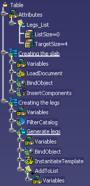
At this stage of the scenario, the Behaviors tab is
similar to the graphic opposite. |
 |
The definition of the behaviors is now over. Save your file and
generate your workbench. (Click
here to display the
generated .CATfct file).
-
Click the Applicative Workbench Generation
icon ( )
to generate a user workbench. Enter the name of the workbench, Designing
a Table in this example, as well as the workbench type, Product
in this scenario. )
to generate a user workbench. Enter the name of the workbench, Designing
a Table in this example, as well as the workbench type, Product
in this scenario.
-
From the Tools>Options>Knowledgeware>Business
Knowledge Template menu, select All Users from the
Access Rights scrolling list and click OK to work in a User
environment.
-
Click the root of the specification tree, then the
 icon, then the root of
the specification tree, and click the Table icon to type the product. icon, then the root of
the specification tree, and click the Table icon to type the product.
-
Right-click Table (Product1) and select
Table(Product1) object>Creating the slab. The File selection window
is displayed. Select the
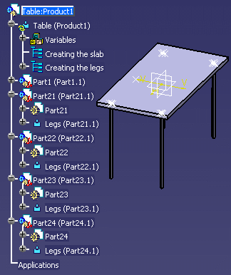
BktSlab.CATPart file. The following image is displayed.
-
Right-click Table (Product1) and select
Table(Product1) object>Creating the legs. The Catalog Browser is
displayed. Double-Click ComponentFamily.2, and Document Template.1. The
Insert Object dialog box is displayed.
-
In the geometry, click one point and click OK.
The first leg is instantiated.
-
Repeat the same operation with the other legs. The
instantiation window i.e. the Insert object dialog box is displayed 4
times, enabling you to instantiate the 4 legs.
-
Click Close. The 4 legs are instantiated as
defined when creating the Table type.
 |
Note that:
- The document templates are instantiated and that the parts are
typed according to the type defined in the .CATfct file.
- If you edit the component list located below the table product,
4 instances are present.
|
|
![]()